Steamly S2-S/Avionics
SECTION 3. AVIONICS
Contents
1 Radios
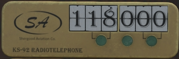
A 760 channel COM radio (Figure 1) is mounted near the bottom of the middle panel. The COM radio operates in the VHF band between 118.000 Mhz and 136.975 Mhz and has a maximum range of about 15 regions (3.75 km). As a station approaches the maximum range, reception quality will begin to degrade.
The selected frequency is shown in the middle of the radio. Three buttons under the displayed frequency cycle through different combinations of digits. In addition the chat commands "com" can be used to select a frequency. For example:
com 128.125
would set the COM frequency to 128.125 MHz.
Each airport in SL, has a specific set of frequencies associated with it that may be viewed by clicking on an airport icon on the Shergood Aviation Map. These frequencies are:
CTAF/TWR - When an airport has an operating control tower, this frequency is used for communication with the control tower. When no control tower is in service, this frequency is the CTAF (Common Traffic Advisory Frequency). The CTAF is used to self-announce position relative to the airport
ATIS - Automatic Terminal Information Service - This frequency broadcasts weather and notam information about an airport.
Ground - This frequency is used for ground communication at an airport. Normally this frequency is used only when a control tower is in service. In other cases, the CTAF is used.
VOR - Frequency of the VOR navigation beacon at an airport. This frequency is used by the NAV radios. (Nav radios not installed on this aircraft)
2 GPS
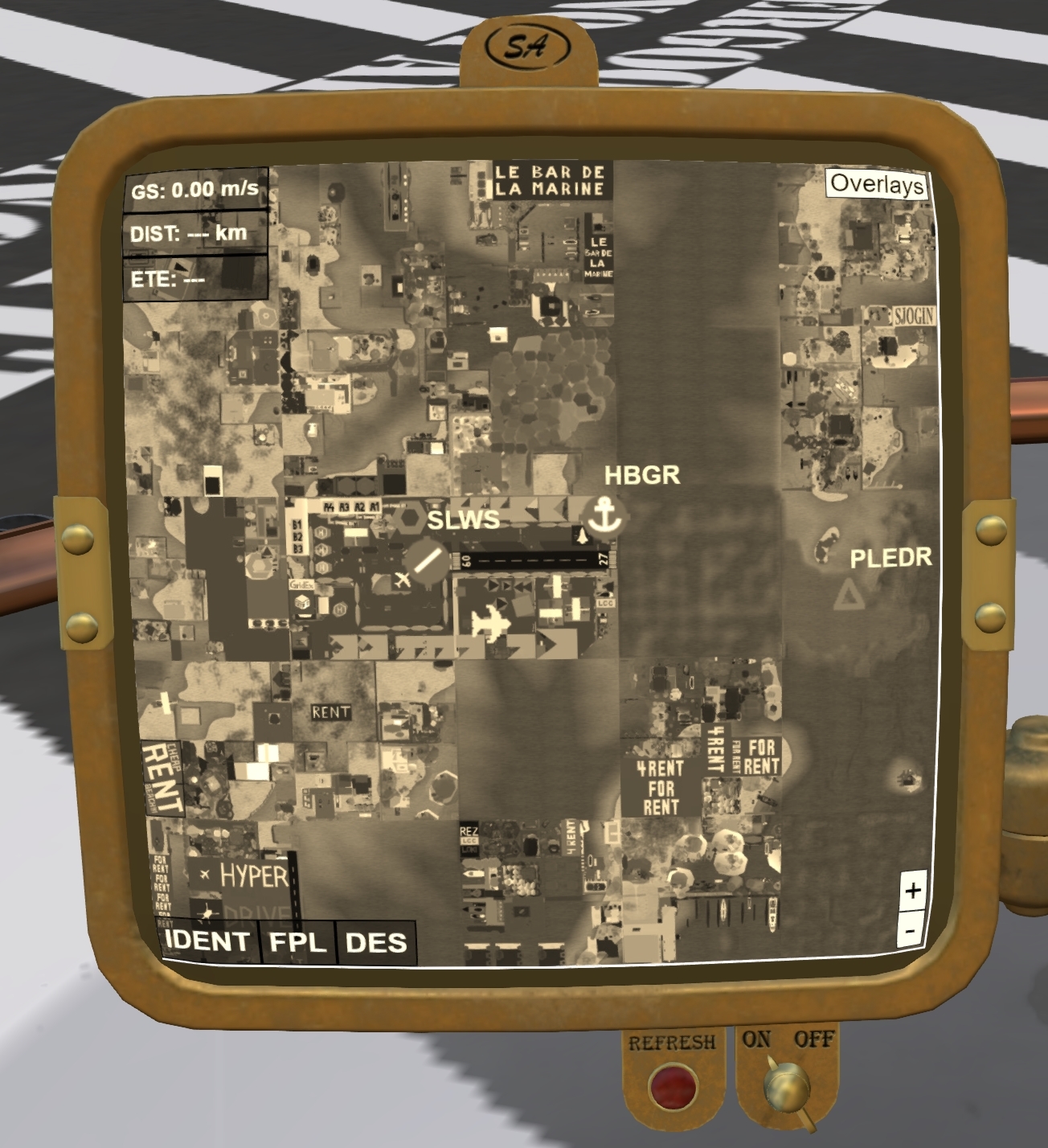
A GPS (Figure 2) can be optionally fitted in front of the passenger seat of the aircraft, where it is visible to the pilot without compromising pilot visibility. To install the GPS, click the front glass to get the main menu, select the "@Options" menu, then enable " GPS".
The GPS uses prim media and must ensure your viewer has media enabled, and you must click the face to activate the media. Once media is enabled, ensure that power is on, and the switch under the display is in the ON position.
Once turned on, the GPS panel functions almost identically to the Advanced GPS HUD other than the lack of integrated transponder features.
3 Transponder
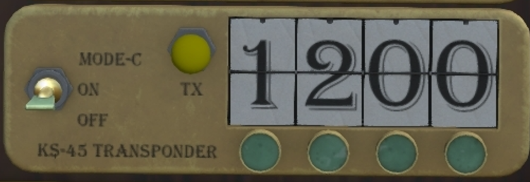
A KS-45 mode-C transponder is located at the base of the middle panel. A three-position switch can select between OFF, ON and MODE-C settings. The transponder operates off the DC bus and is protected by the RADIO circuit breaker. When the switch is in the ON position, only position data is transmitted. When the switch is in the MODE-C position, both altitude and position data is transmitted. The squawk code is changed by clicking on the buttons under each digit. Alternatively the "x n" chat command can be used. For example, to set the squawk code to 1200, use the chat command:
x 1200
A yellow light labeled "TX" will flash each time transponder data is transmitted.
4 ELT
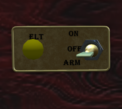
An ELT (Emergency Locator Transmitter) is installed in order to alert rescue personnel in the event of a crash. The ELT is controlled through a panel on the right side of the main console. The panel consists of a three position switch with the settings:
- ARM - Normal operating position. When in this position the ELT will detect sudden accelerations, and transmit an emergency signal once triggered.
- OFF - Disabled the ELT preventing any triggering or transmission of the emergency signal. Also used to reset the ELT after an activation.
- ON - Continuously transmits an emergency signal. This setting should only be used briefly for testing, or when a rescue is required, but the forced landing was not hard enough to trigger an alert.
A yellow light on the ELT will flash when the ELT has been triggered. It is good practice to ensure this light is not flashing after landing, in particular if a hard landing was experienced.


