H-34 Choctaw/All Weather Operations
SECTION 11. ALL WEATHER OPERATIONS
Contents
1 Weather Commands
Weather chat commands can be used to set visibility conditions. When in IMC, the inside windows will be made opaque to simulate flight in fog or clouds. You can also set a "ceiling", the height of the cloud layer. This feature can be used in conjunction with the ILS approach system.
The temperature and humidity commands can be used to override the normal weather model to experience the effects of hot or cold weather.
| Command | Description |
|---|---|
| wx vmc | Sets the current weather to VMC (Visual Meteorological Conditions) |
| wx imc | Sets the current weather to IMC (Instrument Meteorological Conditions) |
| wx ceil n | Sets the current ceiling to the specified height in feet |
| wx temp n | Sets outside temperature to n C, and set static temp/humidity mode |
| wx humidity n | Sets outside humidity to n%, and set static temp/humidity mode |
| wx auto | Sets auto temperature/humidity mode |
2 Warm Weather Operations
Pilots should be mindful that
3 Cold Weather Operations
This section describes aircraft systems for cold-weather operations.
3.1 Oil Dilution System
When a cold weather start (below 10C) is anticipated for the next start-up of the aircraft, the oil dilution system should be used during shutdown to mix fuel into the oil lines. This system will inject fuel into the oil system to reduce the oil viscosity making starting easier and reducing wear on the engine during cold-weather operations.
Use the following procedure:
- Idle engine at 1000 RPM until oil temperature falls below 40C.
- Fuel booster switch - ON
- OIL DIL - ON
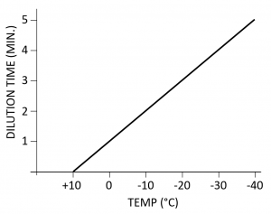
- Wait for the time period prescribed in the table shown in <xr id="fig:oil-dilution"> based on the anticipated temperature at next engine start.
- Shut down engine normally
- OIL DIL - OFF
3.2 Preheater
When outside temperatures are 10C or below, and performing oil dilution on the previous shutdown was not performed, special cold-weather start procedures are recommended.
- Covers - Apply (select Covers from the @Get menu)
- Start APU if equipped (or connect GPU if APU is not available)
- DC Power - BATT ONLY
- CABIN HEAT - HIGH
- Time to preheat will depend on the outside temperature. It may require up to 15 min. in very cold (e.g., -40C) conditions.
- CABIN HEAT - OFF
- DC Power - OFF
- Covers - Remove
- Start using normal procedures (before heat is lost)
3.3 Pitot Heat
The PITOT HEAT switch on the overhead panel activates an electric heating element in the pitot tube. The heating element is powered by the primary DC bus. The PITOT HEAT should be turned on whenever the outside temperature is below 0C to prevent ice from forming on the pitot tube. An iced up pitot tube will render the airspeed indicator inoperable. Furthermore, and any additional functions depending on airspeed (e.g., the ASE) will also fail to function properly.
3.4 Carburetor Air Lever
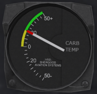
When the temperature shown on the carburetor temperature gauge (Figure 3) is between 0C and 20C (yellow arc), carburetor heat should be applied to prevent icing. Since the carburetor temperature gauge shows the temperature at the intake, the temperature in the carburetor venturi can be lower than at the intake, thus the risk of ice build-up in this range. When the outside temperature is below 0C, then any moisture in the incoming air is already frozen, and thus there is no risk of ice build-up in the carburetor.
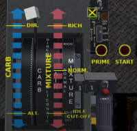
Carburetor heat is controlled through the carburetor air lever (see Figure 4) located on the left side of the engine control quadrant mounted on a console between the pilot and copilot seats. The lever has a white handle on the end and is marked CARBURETOR next to the lever. It is marked DIRECT at the forward end, and ALTERNATE at the aft end of the scale. The lever is used to provide heated air to the carburetor to prevent icing. In the DIRECT position, air is drawn directly through the air intake. As the lever is moved toward the ALTERNATE position, part of the intake air is redirected through a duct heated by the engine exhaust manifold. Use of carburetor heat may require increased throttle due to the lower density of the warm air entering the engine.
Clicking on the engine quadrant will bring up an overlay with scales for the mixture, carburetor heat and the starter and primer buttons. Carburetor air is controlled through the blue scale on the overlay.


