SL Helicopter Flying Handbook/Helicopter Flight Controls
SECTION 3. Helicopter Flight Controls
Contents
1 Introduction
A pilot maneuvers a helicopter using three primary flight controls: the collective, the cyclic and the anti-torque pedals. In addition, the pilot must also manage the throttle to maintain rotor RPM. In this section, these controls are described in detail. We will assume a helicopter with a single counter-clockwise rotating rotor for the purpose of the explanations here. In a helicopter with a clockwise rotating rotor, left and right should be interchanged in the explanations.
2 Collective
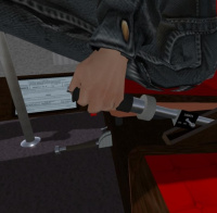
The collective controls the total thrust generated by the helicopter and is normally used to control altitude. The collective is located to the left of the pilot, and is usually a lever that can be raised and lowered with the left hand. The collective increases the pitch of the blades "collectively" around the entire rotation of the blades thus increasing the total thrust developed by the rotor system. This is done through a series of linkages between the collective lever and bottom side of a swash plate (see below) which translates control inputs to the rotor blades.
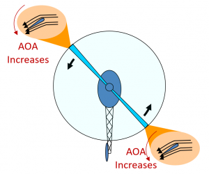
As the collective is raised, the angle of incidence of each blade is increased (see Figure 2). Similarly, lowering the collective decreases the angle of incidence of each blade. An increase of angle of incidence will normally also increase angle of attack, and drag. The increased drag causes the rotor RPM to drop. In order to compensate for this drop in RPM, power must be increased. This is normally accomplished by control of the throttle, or through a governor which automatically adjusts the power to maintain proper RPM.
3 Throttle Control
Helicopters are designed to operate at a specific RPM, or a narrow range of RPMs. The function of the throttle is to maintain the RPM within this range. If the helicopter is not equipped with a governor or correlator, the pilot must do this manually. The throttle is usually a twist grip located on the end of the collective. In most helicopters, rotating the grip away from the pilot will increase power, and rotating it toward the pilot will decrease power.
When collective is increased, the amount of engine power needed to maintain the target RPM will decrease. The pilot must simultaneously increase throttle to maintain proper RPM. When collective is decreased, the engine power requirement is decreased. The pilot must simultaneously decrease throttle to prevent the rotors from overspeeding.
In a piston helicopter, collective pitch is the primary control affecting manifold pressure (MP), and throttle is the primary control affecting RPM. The pilot should manage both RPM and manifold pressure while flying as described in the following table:
| if rpm is | and MP is | Remedy |
|---|---|---|
| LOW | LOW | Increase throttle |
| LOW | HIGH | Lower collective |
| HIGH | LOW | Raise collective |
| HIGH | HIGH | Decrease throttle |
3.1 Correlator
A correlator is a mechanical linkage that automatically adds throttle when the collective is increased, and reduces throttle when the collective is lowered. The adjustments from a correlator are usually approximate and must be fine tuned by the pilot.
3.2 Governor
A governor an electronic device that measures the rotor RPM, and increases or decreases the throttle through an electric servo to maintain a specific RPM. In helicopters equipped with a governor, the governor can be engaged through a switch, or may come on automatically when the RPM enters a specific range. In all cases, it is possible for the pilot to manually override the governor by manually moving the throttle.
4 Cyclic
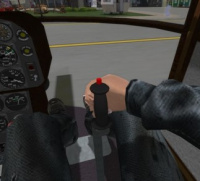
The cyclic is a stick that can be moved like a joystick forward and back, and left and right to control the direction of thrust from the main rotor. The cyclic is usually a stick mounted on the floor between the pilot's legs, though some helicopters such as the Robinson models use a T-stick cyclic mounted in the center of the cabin with a T-bar on the top.
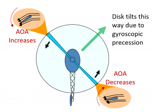
The control is called the cyclic because it varies the pitch of the rotor blades as a function of their angle with the rotor mast over the course of a revolution (see Figure 4). This results in an unequal lift/thrust from the blade is it rotates causing the rotor disk to tilt in the direction the pilot pushes the cyclic. When the rotor disk tilts, it diverts some of its total thrust to a horizontal component giving the helicopter a thrust in the direction the cyclic was pushed. Because the rotor blades act like a gyro, the direction the helicopter tils is 90 degrees from where the maximum pitch up is located.
5 The Swash Plate
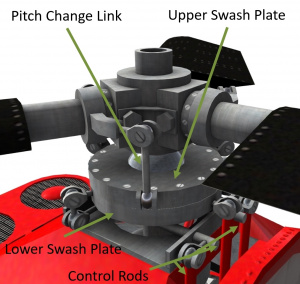
Control inputs in a helicopter are transmitted to the rotor system by means of a swash plate (Figure 5). The swash plate consists of a lower non-rotating plate, and an upper rotating plate. Control rods from the collective and cyclic attach to the non-rotating lower swash plate and cause it to move. The collective raises and lowers the plate, while the cyclic causes the plate to tilt in the direction the cyclic was pushed. The upper plate rotates with the rotor blades, and mirrors the position and orientation of the lower plate. Pitch change rods from each rotor blade attach to the edge of the upper swash plate. As they travel around a 360 degree rotation, the pitch rods are pushed and pulled thus decreasing or increasing the blade pitch over a rotation.
6 Anti-Torque Pedals
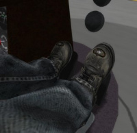
Antitorque Pedals are located on the floor in the same position rudder pedals would be in a fixed-wing aircraft. They are typically controlled with the feet and move together. Pushing one pedal causes the other to move forward and vice-versa. The main purpose of the pedals is to counter-act thrust from the main rotor. As was discussed in the previous section, Newton's Third Law states that for every action there is an equal and opposite reaction. The applies to the helicopter fuselage and the power applied to the main rotor. As the main rotor turns counter-clockwise, there is a torque trying to turn the helicopter body clockwise. This manifests itself as a right yaw if left unchecked.
In order to make flight possible and compensate for this yaw, single rotor helicopters are equipped with some sort of anti-torque system. The most common anti-torque system is a tail rotor. The anti-torque pedals control the pitch of the tail rotor, and thus the thrust from the tail rotor. The pitch can be positive, zero or negative allowing the pedals to cause the helicopter to yaw left or right in the direction on which the pedal was pressed.
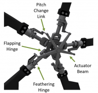
Control inputs from the pedals are transmitted to the tail rotor blades through a swash plate in the tail rotor system (Figure 7). A flapping hinge on each blade (or delta hinge on a two bladed tail rotor) allow blades to “flap” move forward and back in the tail rotor disk plane. Flapping is necessary to compensate for “dissymmetry of lift” which occurs because the airspeed over the advancing side and retreating side of the rotor disk is different at cruise speeds.
7 Shergood Flight Control System
This section details the flight controls for the Shergood Helicopter Flight System in SL. The controls as described here are a general description. See the flight manual for your specific make/model for details. The Shergood Flight System supports two separate control schemes: Keyboard-based and HUD-based. The control scheme is set in the @Options menu. Regardless of the scheme selected, controls can also be moved through the HUD by pressing and holding the left mouse button and dragging the appropriate slider in the HUD. In both control schemes, some key commands are activated through gestures included in a box as part of the product carton. Key commands requiring a gesture are marked with a [G] in the key command lists below.
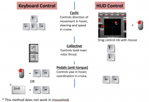
An overview of the flight controls using the two primary controls schemes, keyboard and hud, are shown in Figure 8.
7.1 Flight HUD
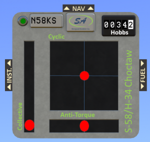
All Shergood helicopters use the same layout for the base HUD (see Figure 9). The HUD shows the position for each of the three primary controls. A red dot for each control shows the current position for that control. Controls can be moved by directly click or dragging a control in the HUD, or through the key commands. Note that there may be some delay between clicking in the HUD, and the red dot moving. The red dot shows the actual current position of the control as received from the aircraft. There is a round-trip delay between when you click in the HUD, and when the effect is displayed in the HUD.
The large square area is for the cyclic. Forward cyclic is in the top-part of the square, and aft cyclic in the bottom half. Reference lines show the position of neutral cyclic. The collective is normally displayed as a vertical bar to the left of the cyclic area. The anti-torque control is normally displayed as a horizontal bar under the cyclic. The pedal scale is also marked with a reference line to show neutral pedal.
7.2 CONTROLS LAYOUT "K" (KEYBOARD)
Keyboard control features a traditional layout with the cyclic controlled by the arrow keys.
| Key | Description |
|---|---|
| Left/Right/Up/Down (or A/D/W/S) | cyclic (Left/Right/Forward.Back) |
| PgUp/PgDown (or E/C) | Collective (Up/Down) |
| L. Mouse + Left/Right (or A/D) | Pedals (left/right)* |
| Shift-Left/Shift-Right | Alternate pedal control (not available in mouselook) |
| Z/X | Alternate pedal keys (left/right) [G] |
| . | Center cyclic [G] |
| p | Toggle camera view [G] |
| q | Toggle fine control [G] |
| t | Toggle mouselook-touch [G] |
- NOTE ON PEDALS: Because the left mouse button is intercepted by the touch scripts in the heli, the L.Mouse + Arrow key combination will only work in mouselook, or in external view modes. There is also a "mouselook touch" mode that is toggled by the "mlt" chat command. This toggles whether mouse clicks while in mouselook affect switches and buttons in the cockpit, or are used for pedals.
7.3 CONTROL LAYOUT "H" (HUD)
HUD control is designed to be used with the left hand on the WASD buttons, and right hand on the mouse controlling the cyclic in the HUD (by dragging the red dot on the HUD). It is also possible to use gestures for the JKLI buttons to control cyclic with in this mode.
| Key | Description |
|---|---|
| Up/Down (or W/S) | Collective up/down. |
| Left/Right (or A/D) | Anti-torque pedals. |
| J/L/I/K | *Cyclic left/right/forward/back. [G] |
| . | Center cyclic [G] |
| p | Toggle camera view [G] |
| q | Toggle fine control [G] |
| t | Toggle mouselook-touch [G] |
7.4 Flight Control Chat Commands
This section describes basic chat commands related to helicopter control that are available in most Shergood helicopters.
| Command | Description |
|---|---|
| cycen | Center the cyclic |
| pedcen | Center the pedals |
| cv/cv0/cv1/cv2/cv3 | Change camera view: toggle/cockpit/behind/overhead/underside |
| fc/fc0/fc1/fc2 | Fine control: toggle/off/fine/very-fine |
| mlt | Toggle "mouse look touch" |
| hud | Get copy of hud |
