Difference between revisions of "H-34 Choctaw/Systems"
(→Alternating Current Power Supply System) |
(→Battery Bus) |
||
| Line 265: | Line 265: | ||
====== Battery Bus ====== | ====== Battery Bus ====== | ||
| − | The battery bus supplies power to the pilot's | + | The battery bus supplies power to the pilot's dome light, the instrument emergency lights and the crew alarm switch. The battery bus is continuously energized by the battery, regardless of the position of the battery-generator switch. |
===== Battery-Generator Switch ===== | ===== Battery-Generator Switch ===== | ||
Revision as of 18:45, 30 June 2021
SECTION 2. SYSTEMS
Contents
- 1 Helicopter
- 2 Landing Gear System
- 3 Engines and Related Systems
- 4 Fuel System
- 5 Electrical System
- 6 Flight Controls and AFCS
- 7 Hydraulic Systems
- 8 Power Train System
1 Helicopter
1.1 General
The Shergood H-34/S-58 is a piston engine helicopter designed for transportation of cargo and for search-and-rescue operations in day, night, visual and instrument conditions. The helicopter is powered by a 1,525 hp Wright R-1820-84 Cyclone rotary engine mounted in the nose of the aircraft. A drive shaft from the engine feeds diagonally up to the main transmission mounted under the main rotors. Fuel is carried by three cells on the belly of the aircraft. An entrance door is located on the forward right side of the main cabin with a hydraulic winch mounted over the door.
1.2 Gross Weight
The maximum gross weight is 13,300 pounds.
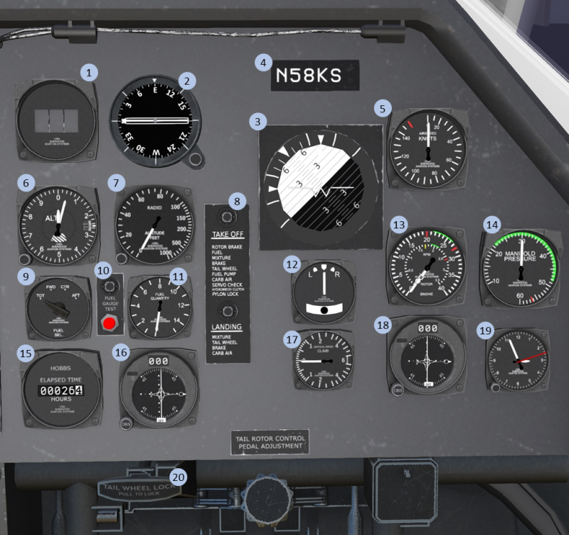
1.3 Pilot-Side Instrument Panel
| 1. DME | 2. RMI | 3. Attitude Indicator | 4. Tail-Number plate |
| 5. Airspeed Indicator | 6. Altimeter | 7. Radio Altimeter | 8. Checklist |
| 9. Fuel Indicator Selector | 10. Fuel Indicator Test | 11. Fuel Indicator | 12. Turn/Slip Indicator |
| 13. RPM Indicator | 14. Manifold Pressure | 15. HOBBS Time | 16. #2 VOR |
| 17. VSI | 18. #1 VOR | 19. 8-Day Clock | 20. Tail Wheel Lock |
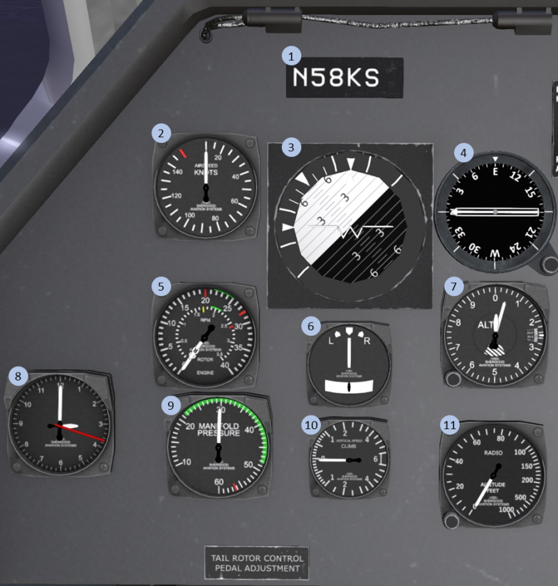
1.4 Copilot-Side Instrument Panel
| 1. Tail-Number plate | 2. Airspeed Indicator | 3. Attitude Indicator | 4. RMI |
| 5. Airspeed Indicator | 6. Turn/Slip Indicator | 7. Altimeter | 8. 8-Day Clock |
| 9.Manifold Pressure | 10. VSI | 11. Radio Altimeter |
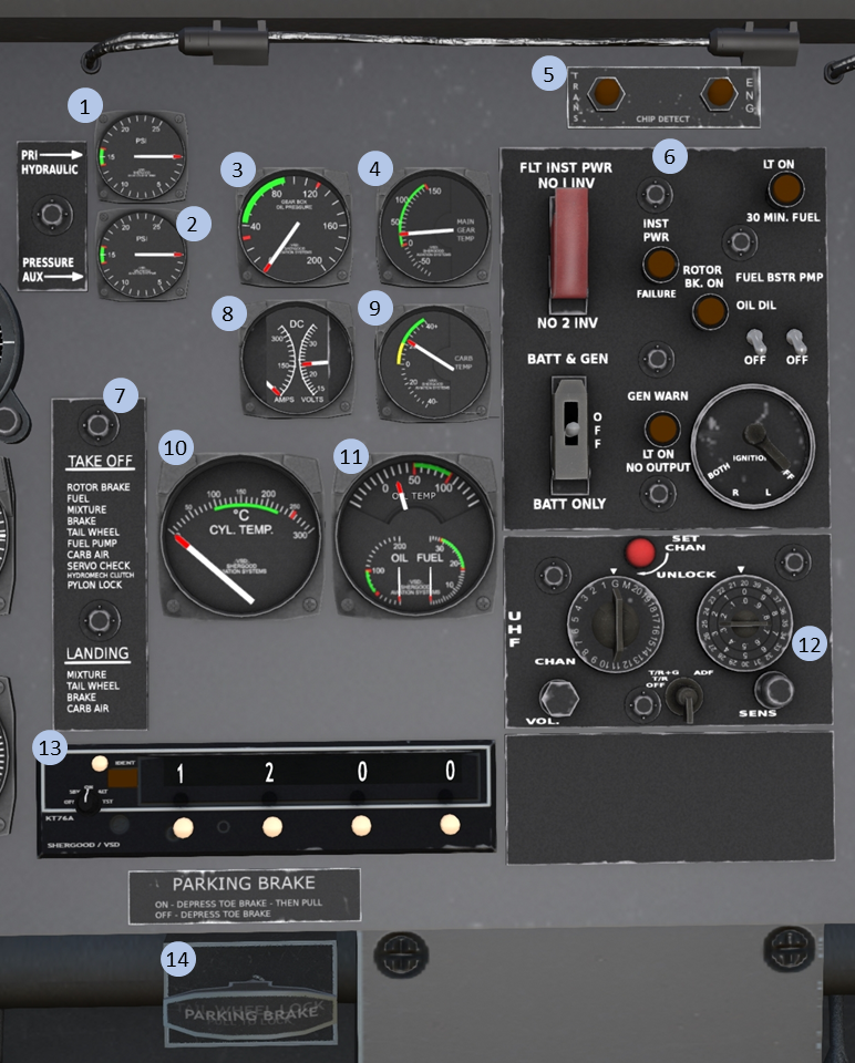
1.5 Center Instrument Panel
| 1. Pri. Hyd. Press | 2. Aux. Hyd. Press | 3. Main Trans. Oil Press | 4. Main Trans. Oil Press |
| 5. Chip Indicator | 6. Main Switch Panel | 7. Checklist | 8. DC Volts/Amps |
| 9. Carburetor Temp. | 10. Cylinder Temp. | 11. Oil Temp/Press, Fuel Press | 12. UHF Radio |
| 13. Transponder | 14. Parking Brake |
1.6 Overhead Panel
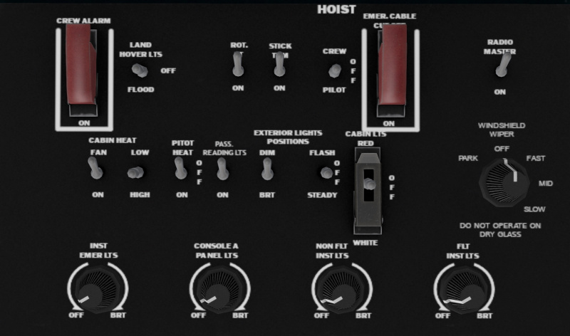
The overhead panel includes various miscellaneous switches including most of the lighting controls, and controls for the hoist and heating systems.
2 Landing Gear System
The S-58 has a fixed landing gear system with two main wheels in the front and a tail wheel in the rear.
2.1 Parking Brake
A parking brake is located in front of the co-pilot seat under the center console (Item #14 in Figure 3). Activating the parking brake will increase resistance to ground movement. Click the handle to toggle its position, or use the chat command:
s brake
to toggle it.
2.2 Tailwheel Lock
A tailwheel lock is located on the pilot side below the pilot console. Click the handle to toggle its position, or use the chat command:
s taillock
to toggle it. The tailwheel lock should be used during rotor engagement to prevent the helicopter from turning on the ground during the high-torque stages of engagement.
3 Engines and Related Systems
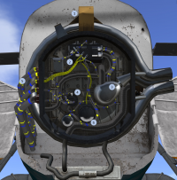
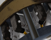
The S-58 is powered by a 1,525 hp Wright R-1820-84 Cyclone, a 9-cylinder radial engine mounted in the nose of the aircraft (see Figure 5). A drive shaft oriented at 45 degrees passes through he main cabin up to the main transmission. The cylinders (see Figure 6) are arranged around the drive shaft of the engines at 40 degree intervals. Each cylinder has two spark plugs, each powered by a different engine driven magneto.
The engine compartment is accessed by two large doors at the nose of the aircraft. Engine accessories including the carburetor, dual magnetos, starter, and auxiliary hydraulic pump are mounted on the front of the engine.
3.1 Carburetor
A double-barrel, downdraft, injection-type carburetor is mounted at the entrance to the supercharger inlet.
3.1.1 Throttle
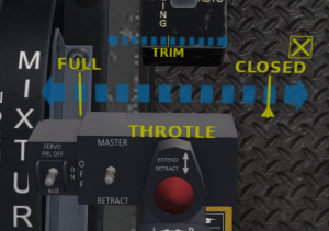
The throttle is controlled by a twist grip on the end of the pilot and copilot's collective. Clicking on the grip area of the collective will bring up a transparent overlay through which you can control the throttle (see Figure 7). The overlay has a large scale marked FULL and one end and CLOSED at the other. Clicking on this scale will move the throttle to that position. A small yellow triangle under the scale shows the current throttle position.
A smaller scale marked "TRIM" above the throttle scale can be used to make small throttle adjustments. Clicking left of the centerline will increase the throttle by an amount proportional to the distance from the centerline, while clicking to the right of the centerline will decrease the throttle by a proportional amount.
The gesture pack included with the aircraft also includes the following three gestures for controlling the throttle:
| Gesture | Description |
|---|---|
| r | Increase throttle |
| v | Decrease throttle |
| 0 | Close throttle |
The throttle is partially linked to the collective by a correlator which will increase throttle as the collective is pulled, and decrease throttle as the collective is lowered. In addition a throttle governor will engage above 2100 RPM to keep the engine, initially, at approximately 2500 RPM. Once the governor control is established, the pilot may change the governor setpoint by manually changing the throttle between 2100 and 2800 RPM. After a manual throttle change, the governor will reengage at the new RPM. To disengage the governor, roll the throttle below 2100 RPM.
3.1.2 Mixture Control Lever
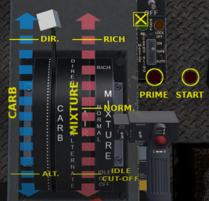
The mixture control lever (see Figure 8) is located on the right side of an engine control quadrant mounted on a console between the pilot and copilot seats. The lever has a red handle on the end and is marked MIXTURE next to the lever. It has three positions marked IDLE CUT-OFF, NORM and RICH. The RICH position is used for ground operations and take-off and landing. The NORM position should be used while in cruise flight. The IDLE CUT-OFF position will cut fuel to the engine for shutdown and securing.
Clicking on the engine quadrant will bring up an overlay with scales for the mixture, carburetor heat and the starter and primer buttons. Mixture is controlled through the red scale on the overlay. Click on the X in the upper right corner to hide the overlay.
3.1.3 Carburetor Air Lever
The carburetor air lever (see Figure 8) is located on the left side of an engine control quadrant mounted on a console between the pilot and copilot seats. The lever has a white handle on the end and is marked CARBURETOR next to the lever. It is marked DIRECT at the forward end, and ALTERNATE at the aft end of the scale. The lever is used to provide heated air to the carburetor to prevent icing. In the DIRECT position, air is drawn directly through the air intake. As the lever is moved toward the ALTERNATE position, part of the intake air is redirected through a duct heated by the engine exhaust manifold. When the carburetor temperature is between 0C and 20C (yellow arc), carburetor heat should be applied to prevent icing. Use of carburetor heat may require increased throttle due to the lower density of the warm air entering the engine.
Clicking on the engine quadrant will bring up an overlay with scales for the mixture, carburetor heat and the starter and primer buttons. Carburetor air is controlled through the blue scale on the overlay.
3.2 Ignition Systems
The ignition system consists of a dual magneto, an ignition harness carrying current to the spark plug on each cylinder, an induction vibrator, and an ignition switch. When the starter switch is depressed, and the ignition switch is in the R or BOTH position, the induction vibrator supplies current to the spark plugs for starting. Once the engine has started, current for the spark plugs is supplied by the engine-driven magnetos.
3.2.1 Ignition Switch
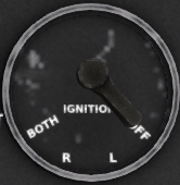
The ignition switch (see Figure 9) is located in the pilot's compartment on the main switch panel. Marked positions of the switch are: OFF, L, R and BOTH. The switch position may be selected by clicking on the marked position around the switch. When the switch is in the L position, the rear spark plugs of each cylinder are firing. When the switch is in the R position, the front spark plugs are firing, and when the switch is in the BOTH position, all spark plugs are firing.
3.3 Engine Priming System
The engine priming system is incorporated into the carburetor and consists of a two-point priming system controlled by a solenoid valve and an engine prime button. The priming system operates on DC current form the secondary bus. Fuel pressure for priming is supplied by the fuel boost pump.
3.4 Starter
The starter system consists of the starter motor, starter relay, throttle limit switch and starter button. Pressing the starter button closes a relay permitting the starter to be energized by the secondary DC Bus. The limit switch disables the starter if the collective is not full down, and the throttle is not full closed (or slightly cracked).
Normal starts are performed using an external power source. To start without external power, the guard on the DC master switch must be opened and the switch placed in the BATT ONLY position. The starter button also energizes the vibrator in the ignition system when the ignition switch is in the BOTH or R positions. This provides an initial spark on the spark plugs for starting.
3.5 Engine Chip Detector Warning Light
A chip detector warning light is located on a small panel above the main switch panel (Item #5, Figure 3). When the light is illuminated, it indicates that metal fragments have been detected circulating in the engine oil system. This indicates the presents of excessive engine wear and high probability of an impending engine failure.
3.6 Primary Engine Instruments
3.7 Secondary Engine Instruments
4 Fuel System
5 Electrical System
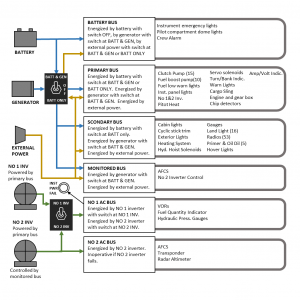
Electrical power is supplied by two basic systems: a 28-vold direct current system and a 115-volt alternating current system. Equipment operating from each system is shown in Figure 11.
5.1 Direct Current Power Supply System
Power for the operation of dc equipment is supplied by three sources: the battery, the generator and an external power supply system. Power is distributed through four buses: primary, secondary, monitored and a battery bus. A network of breakers and relays separate the buses.
5.1.1 Direct Current Power Sources
5.1.1.1 Battery
The 24-volt, 24-amp-hour battery is located on the left side of the clutch compartment behind the engine. It is accessed through a side panel behind the engine compartment. Battery power can be used for limited ground operation, including engine start when external power is not available. It is also used as an emergency power source in the event of an in-flight generator failure.
5.1.1.2 Generator
A 30-volt, 400-amp generator is located on the aft side of the main transmission and is driven by the accessory section of the transmission. The generator is the main source of power for the helicopter once the clutch has been engaged and the rotor is at normal operating RPM. The generator, being power by the main gear box, will continue to provide power during autorotation.
5.1.1.3 External Power Receptacle
The 28-volt external power receptacle is located on the right-hand side of the fuselage, forward of the cabin door. External power should be used for all ground operation until after clutch engagement to prevent unnecessary discharging of the battery.
5.1.2 Direct Current Distribution
Power for the operation of DC equipment is distributed through the following four buses.
5.1.2.1 Primary Bus
The primary bus supplies power for the DC flight instruments and all equipment necessary for the safety of flight. The primary bus may be energized from all three power sources. When external power is connected, it connects directly to the primary bus. Battery power is connected to the primary bus whenever the battery-generator switch is in either the BATT & GEN or the BATT ONLY positions. Generator power is supplied to the primary bus whenever the battery-generator switch is in the BATT & GEN position. In the event of a generator failure, battery power will be automatically connected to the primary bus.
5.1.2.2 Secondary Bus
The secondary bus supplies power for the auxiliary equipment and equipment not necessary for the safety of flight. The secondary bus is energized by external power through a secondary bus relay that connects the primary and secondary buses when external power is attached. Generator power is supplied to the secondary bus through the same relay once the generator is producing power. In the event of a generator failure during flight with the battery-generator switch in the BATT & GEN position, the secondary bus relay will disconnect and all equipment on the secondary bus will be inoperative. This will minimize the load on the battery and conserve battery power for the essential equipment. If it is necessary to use equipment on the secondary bus after a generator failure, the battery-generator switch can be placed in the BATT ONLY position to close the secondary bus relay and energize the secondary bus from the battery.
5.1.2.3 Monitored Bus
The monitored bus supplies power to the control circuits for equipment that is not essential to the safety of flight, and which has power demands that are too heavy for operation by the battery. The monitored bus is powered by a relay that is open only when external power is attached, or the generator is producing power.
5.1.2.4 Battery Bus
The battery bus supplies power to the pilot's dome light, the instrument emergency lights and the crew alarm switch. The battery bus is continuously energized by the battery, regardless of the position of the battery-generator switch.
5.1.3 Battery-Generator Switch
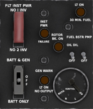
The battery-generator switch, covered by a switch guard, is located on the main switch panel (Figure 12). The switch has three positions marked: BATT & GEN, OFF and BATT ONLY. The switch, in conjunction with the generator-actuated relays, controls the distribution of power to the various DC busses as follows:
- BATT & GEN - When external power is not connected, battery power is supplied to the primary and battery busses only. When external power is connected, or the generator is producing power, all DC busses are energized and the battery will charge.
- BATT ONLY - When external power is not connected, battery power is supplied the the primary, secondary and battery buses only. When external power is connected, power is supplied to all DC busses and the battery will charge.
- OFF - When external power is not connected, only the battery bus is energized. When external power is connected, the primary, secondary and monitored buses will be powered by the external source, but the battery will not charge.
5.1.4 Generator Warning Light
The generator warning light is located on the main switch panel. The light is on whenever the primary bus is energized by other than generator power. In normal flight operations with the battery-generator switch in the BATT & GEN positions, the warning light will come on when generator power falls below a threshold indicating a partial or total generator failure. In this condition, power is lost to the secondary and monitor buses. Power may be restored to the secondary bus by moving the battery-generator switch to the BATT-ONLY position. The warning light is of the push-to-test type.
5.1.5 Volt-Ammeter
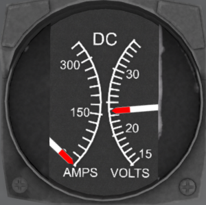
The volt-ammeter consists of a combined volt-meter and ammeter mounted in a single case on the instrument panel (Figure 13). The voltmeter indicates the voltage on the primary bus. The voltage should be between 22 and 24 volts when operating off the battery and 28 volts when the generator or external power is being used. The ammeter indicates the load being placed on the generator or battery by all equipment being used in the helicopter.
5.2 Alternating Current Power Supply System
Power for the AC system is provided by two 115-volt inverters and distributed through two AC buses. Both inverters are powered by the primary DC bus, but the No 2 inverter is controlled by the monitored bus and requires it to function. The inverters are located in the left-hand side of the clutch compartment just aft of the engine compartment. The No 1 Inverter supplies 250 VA while the No 1 inverter supplies 2500 VA. The No 1 Inverter supplies power for items essential for safe flight, while the No 2 Inverter supplies power for non-essential equipment such as the AFCS. In normal operation, the No 1 Inverter powers the No 1 AC bus and the No 2 Inverter powers the No 2 AC bus. A guarded switch on the main switch panel labeled FLT INST PWR can be used to power the No 1 AC bus from the No 2 inverter in the event that the No 1 inverter fails. This switch is normally left in the NO 1 INV position. When it is placed in the No 2 INV position, the No 2 Inverter supplies both AC busses.
An instrument power failure light labeled INST PWR FAILURE is located to the right of the switch. This light will illuminate
