Difference between revisions of "H-34 Choctaw/Avionics"
(→Tracking a VOR Course) |
(→Tracking a VOR Course) |
||
| Line 63: | Line 63: | ||
|} | |} | ||
| − | The white line in the center of the CDI, will deflect left or right to indicate the position of the aircraft relative to the selected radial. The CDI indication in <xr id='fig:hsicdi'/> | + | The white line in the center of the CDI, will deflect left or right to indicate the position of the aircraft relative to the selected radial. Once established on a radial, the CDI shows deflection based on angle from the selected radial. The CDI will be centered when you are on course, and when it is deflected you should turn toward the needle to fly back to the course. Note that the CDI indication does not depend on your actual heading. The CDI indications in <xr id='fig:hsicdi'/> show (a) an aircraft that is left of the 048 radial, with right correction to intercept it; (b) an aircraft that is on the 048 radial, heading toward the station; and (b) and aircraft that is to the right of the 048 radial with left correction to intercept it. |
| − | + | When correcting for a course deviation, you should turn the aircraft toward the CDI with the amount of correction corresponding to the amount of deflection. As you converge on the track, the CDI will move to the center and you should gradually decrease the amount of correction. In general, your correction should not be more than 30 degrees to avoid overshooting the track. | |
| − | |||
| − | |||
| − | |||
| − | |||
==== VOR Zone of Confusion ==== | ==== VOR Zone of Confusion ==== | ||
Revision as of 04:22, 8 July 2021
SECTION 3. AVIONICS
Contents
1.1 Introduction
The S-58 supports VOR (Very High Frequency Omni-Directional Range) navigation. VOR navigation is a ground-based navigation system in which a VOR station transmits a signal that is picked up by a NAV radio (see Figure 2) in the aircraft. The VOR transmits two types of signals, an omni-directional pulse, and a rotating directional pulse. The omni-directional pulse is synchronized to occur when the directional pulse is at magnetic north. By measuring the time between the two pulses, the receiver can determine its relative direction, called a radial, from the VOR station. For SL purposes, a virtual VOR station is "placed" at every airport in the[Shergood Airport Map at the location of the airport marker on the map. See Wikipedia: VOR Omnidirectional range for more details on VOR operation.
1.2 Radials
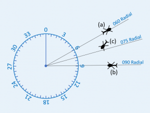
VOR navigation is based on radials. A radial is line of position from the station location, and radiating out on one of 360 directions. Each of these lines of position is called a radial. The radials correspond to the magnetic direction from the station with radial 0 corresponding to North, radial 90 to East, radial 180 to South and radial 270 to West. Figure 1 shows an example of the radials around a station. The aircraft at position (a) is on the 060 radial, the aircraft at position (b) is on the 090 radial, and the aircraft at position (c) is right of course for an inbound approach on radial 075.
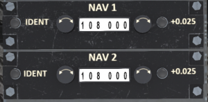
Each VOR station has an associated frequency between 108.0 and 117.95 MHz that is used to select it. The frequency for the VOR at a particular airport can be found on the Shergood Airport Map by clicking on the airport symbol to bring up the data box for that airport. The S-58 is equipped with two NAV radios (see Figure 2) on the lower panel that can be used for VOR-based navigation. The top radio is NAV1 and the bottom radio is NAV2. To enter the frequency for a radio, you can touch the frequency adjustment knobs, or use a chat command. For example, to set the frequency for NAV1 to 117.30, you can use the chat command:
nav nav1 117.30
VOR stations have limited range, typically about 12 SL regions, and stations that are greater than 30 sims apart can share the same frequency. For this reason, it is important that you identify the station that you have selected. Press the IDENT button on the NAV radio to identify the station that is selected. This will produce a chat message of the form:
[10:06:15] SA - S58 v1.0 (N61KS): You hear .... -... --. .-. (HBGR)
with the Morse code for the station, and the station identifier.
1.4 CDI
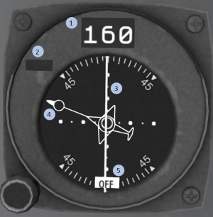
The aircraft is equipped with two CDI indicators (see Figure 3) on the pilot's side of the console. Each CDI is linked to one of the NAV radios. The right-most CDI is linked to the #1 NAV radio, and the right-most CDI is linked to the #2 NAV radio. After selecting a frequency for a CDI, the pilot must also select the radial to be used. This is done with the CRS knob on the CDI. You normally set the active radial with a chat command. For example:
nav crs1 60
will select the 060 radial from the VOR station on the #1 CDI. A radial can be selected as either the radial "FROM" the station, or a radial "TO" the station. The TO radials are 180 degrees from the FROM radials. The selected course will be displayed at the top of the indicator.
The CDI indicator includes the following elements:
- Radial - The radial from or to the VOR the pilot wishes to track.
- TO/FROM Indicator - Indicates if the pilot is flying TO or FROM the VOR based on the selected radial and the aircraft heading
- Course Deviation - Vertical needle that swings left or right to indicate the direction the pilot must fly to intercept the radial. Each large dot represents 10 degrees off-course.
- Relative Course - Heading of the helicopter relative to the selected radial.
- Flag - Will display OFF, if no valid VOR signal is being received.
1.5 Tracking a VOR Course
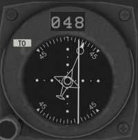
|
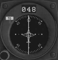
|
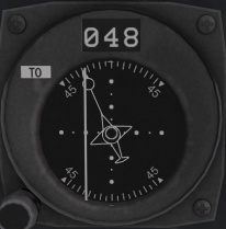
|
| (a) Left Of Course | (b) On Course | (c) Right of Course |
Figure 4: Enroute CDI Indications
| ||
The white line in the center of the CDI, will deflect left or right to indicate the position of the aircraft relative to the selected radial. Once established on a radial, the CDI shows deflection based on angle from the selected radial. The CDI will be centered when you are on course, and when it is deflected you should turn toward the needle to fly back to the course. Note that the CDI indication does not depend on your actual heading. The CDI indications in Figure 4 show (a) an aircraft that is left of the 048 radial, with right correction to intercept it; (b) an aircraft that is on the 048 radial, heading toward the station; and (b) and aircraft that is to the right of the 048 radial with left correction to intercept it.
When correcting for a course deviation, you should turn the aircraft toward the CDI with the amount of correction corresponding to the amount of deflection. As you converge on the track, the CDI will move to the center and you should gradually decrease the amount of correction. In general, your correction should not be more than 30 degrees to avoid overshooting the track.
1.6 VOR Zone of Confusion
Since the CDI shows angle of deviation from the selected radial, the CDI will get more and more sensitive as your approach the VOR. At some point the CDI will become too sensitive to be useful. This is area is called the Zone of Confusion. This usually occurs when flying directly over, or nearly directly over a VOR station. When in the Zone of Confusion, the best practice is not to chase the needle, but to simply maintain your current heading until you are far enough from the station to obtain useful navigation readings. The indication that you have passed a station is signified by the TO/FROM arrow on the HSI flipping from TO to FROM.
1.7 Flying to a VOR Station
If you wish to fly TO a specific VOR, you can first select its frequency, identify it, then turn the CRS knob the CDI is centered with a TO indication. You can the simply turn to the selected radial and fly to the VOR with normal tracking procedures. You can also use the chat commands:
nav obs1 to
To set the #1 CDI to heading to a VOR station (and similarly for the #2 CDI).
1.8 Flying from a VOR Station
If you wish to fly FROM a specific VOR, you can first select its frequency, identify it, then turn the CRS knob the CDI is centered with a FROM indication. You can the simply turn to the selected radial and fly to the VOR with normal tracking procedures. You can also use the chat commands:
nav obs1 from
To set the #1 CDI to heading from a VOR station (and similarly for the #2 CDI).
1.9 Intercepting a VOR Radial
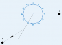
It is sometimes useful to intercept a specific VOR radial. For example, suppose you wished to fly from Point A to Point B in Figure 5 via the selected VOR and approaching that VOR via the 030 inbound radial to avoid a bad sim, orb or other obstruction in the direct path to the VOR. You could do this by selecting 030 as the inbound radial on the CRS knob, then fly a 060 heading until intercepting that radial. As you approached the radial, the CDI would begin to center. You should begin your turn toward the radial course so that the needle is centered at the time you established the inbound course on the radial. ??? shows the indication you might have on your HSI as you approached the inbound course.
In the example here, you would turn toward 030 as the needle center, then fly toward the VOR. When the TO/FROM indicator switches from TO to FROM, you would then change to the outbound course, changing the CRS setting to 090, then tracking out on that radial as usual.
