Difference between revisions of "H-34 Choctaw/All Weather Operations"
(→Warm Weather Operations) |
(→Windshield Wipers) |
||
| Line 80: | Line 80: | ||
=== Windshield Wipers === | === Windshield Wipers === | ||
| − | [[File:S58-wipers.png| | + | [[File:S58-wipers.png|150px|thumb|right| |
<figure id="fig:wipers"><caption> | <figure id="fig:wipers"><caption> | ||
Windshield Wiper Control | Windshield Wiper Control | ||
</caption></figure>]] | </caption></figure>]] | ||
| + | |||
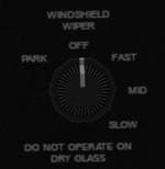
| + | The windshield wipers operate on the secondary DC bus and are controlled by a knob (see <xr id='fig:wipers'/>) on the upper console. The wipers have three speeds: slow, medium and fast. A position labeled PARK can be used to move the wiper to the up/vertical position to move it out of the way of the pilot's view. This position should be used momentarily before turning the wipers off to stow the wipers. The wipers should only be used on wet glass. | ||
=== Warm Weather Operations === | === Warm Weather Operations === | ||
Revision as of 01:31, 16 September 2021
SECTION 11. ALL WEATHER OPERATIONS
Contents
1 Weather in the S-58
Weather is an important factor that affects many aspects of a flight. Preflight preparations should always include a review of current and expected weather conditions along the route of flight. The S-58 is designed to react to a number of potential weather conditions including:
| Condition | Description/Effect |
|---|---|
| Temperature | Affects air density and performance when high and the potential for icing when low. |
| Humidity | Affects potential for carb or pitot tube icing when humidity is high. Also affects the potential for clouds to form. |
| Wind | Affects control inputs needed to maintain a constant position. Potential for vortex-ring-state if landing with a tail wind. |
| Visibility | Affects ability to see the terrain around the aircraft. |
| Barometric Pressure | Affects the altimeter setting needed to calibrate the altimeter. |
| Cloud Height | Height above ground at which visibility will go to zero. |
| Precipitation | Reduces visibility and causes rain drops on glass surfaces that can be cleared with windshield wipers. |
1.1 SL Weather
For more details on weather for Shergood aircraft that support "Advanced Weather", see The SL Helicopter Flying Handbook - Weather.
2 Weather Models
The S-58/H-34 can be operated using either "basic" weather or "advanced" weather. The weather model used is selected from the @Option menu. Turn on the "Adv. Wx" to enable advanced weather. In basic weather mode, relatively mild temperature and humidity variations will be simulated, but no wind or clouds unless requested. With advanced weather, the helicopter will react to wind, clouds, precipitation, etc. These weather systems are described in the following section.
2.1 Basic Weather
When in basic weather mode, chat commands can be used to set various weather conditions (e.g., visibility, temperature, humidity). When in IMC, the inside windows will be made opaque to simulate flight in fog or clouds. You can also set a "ceiling", the height of the cloud layer. This feature can be used in conjunction with the ILS approach system. Within the basic weather system, the following weather submodes can be set:
- auto - variations in temperature and humidity are simulated based on time and position within the helicopter
- static - weather conditions remain static according to user settings. Setting any weather condition to a set value will cause the model to enter static mode.
- disabled - no weather is simulated other than constant 20C temperature.
The chat commands available for basic weather are:
| Command | Description |
|---|---|
| wx auto | Enabled basic weather model |
| wx disabled | Disable all weather |
| wx temp n | Set Temperature to n (Celsius) |
| wx vis n | Set visibility to n miles (0 to 10) |
| wx precip n | Set precipitation intensity to n (0 to 100) |
| wx baro nn.nn | Set sea-level barometric pressure to nn.nn |
| wx ceil n | Set ceiling (cloud bases) to n feet. |
| wx humidity n | Set relative humidity to n percent (0 to 100) |
| wx wind dir speed | Set wind to speed knots (0-40) from direction dir (0-360) |
| wx vmc | Set weather to VMC |
| wx imc | Set weather to IMC |
2.2 Advanced Weather
When advanced weather is enabled, weather will be generated by the Shergood Weather Simulator (SWS). SWS simulates grid-wide weather patterns with charts and data that can be queried at http://www.shergoodaviation.com/weather.php . Each time the aircraft enters a new region, it will query the SWS server for the weather conditions in that region including temperature, humidity, winds, altimeter setting, cloud bases and visibility.
3 Windshield Wipers
The windshield wipers operate on the secondary DC bus and are controlled by a knob (see Figure 1) on the upper console. The wipers have three speeds: slow, medium and fast. A position labeled PARK can be used to move the wiper to the up/vertical position to move it out of the way of the pilot's view. This position should be used momentarily before turning the wipers off to stow the wipers. The wipers should only be used on wet glass.
4 Warm Weather Operations
Pilots should be mindful that in hot and/or humid weather, performance will be decreased due to the increased density altitude. It will require more power/collective to hover, and more power will be required in cruise. Pilots should be aware of the different types of altitude and how they affect performance:
- Indicated Altitude - The altitude as shown on the aircraft altitude indicator.
- True Altitude - The actual altitude of the aircraft above sea level.
- Pressure Altitude - The altitude above the 29.92 in Hg datum plane. Equal to true altitude on a day with standard pressure (29.92 in Hg).
- Density Altitude - The pressure altitude adjusted for temperature. Reflects the expected aircraft performance.
- Absolute Altitude - The altitude of the aircraft above the ground. Displayed on the radar altimeter.
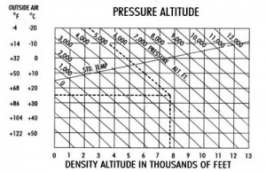
To calculate density altitude, use the chart shown in Figure 2. To use the chart, start on the left-hand side at the outside temperature and move horizontally until reaching the diagonal line for the pressure altitude. Then drop vertically to read the density altitude. In the example shown with dotted lines, the outside temperature is 25C, the pressure altitude is 5300 resulting in a density altitude of 7800.
To a lesser extent than temperature, high humidity can also have an effect on performance as well, particularly in combination with high temperatures. A small buffer should be added to the calculated density altitude when humidity is high.
5 Cold Weather Operations
This section describes aircraft systems for cold-weather operations.
5.1 Oil Dilution System
When a cold weather start (below 10C) is anticipated for the next start-up of the aircraft, the oil dilution system should be used during shutdown to mix fuel into the oil lines. This system will inject fuel into the oil system to reduce the oil viscosity making starting easier and reducing wear on the engine during cold-weather operations.
Use the following procedure:
- Idle engine at 1000 RPM until oil temperature falls below 40C.
- Fuel booster switch - ON
- OIL DIL - ON
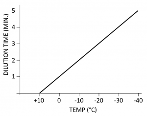
- Wait for the time period prescribed in the table shown in Figure 3 based on the anticipated temperature at next engine start.
- Shut down engine normally
- OIL DIL - OFF
5.2 Preheater
When outside temperatures are 10C or below, and performing oil dilution on the previous shutdown was not performed, special cold-weather start procedures are recommended.
- Covers - Apply (select Covers from the @Get menu)
- Start APU if equipped (or connect GPU if APU is not available)
- DC Power - BATT ONLY
- CABIN HEAT - HIGH
- Time to preheat will depend on the outside temperature. It may require up to 15 min. in very cold (e.g., -40C) conditions.
- CABIN HEAT - OFF
- DC Power - OFF
- Covers - Remove
- Start using normal procedures (before heat is lost)
5.3 Pitot Heat
The PITOT HEAT switch on the overhead panel activates an electric heating element in the pitot tube. The heating element is powered by the primary DC bus. The PITOT HEAT should be turned on whenever the outside temperature is below 0C to prevent ice from forming on the pitot tube. An iced up pitot tube will render the airspeed indicator inoperable. Furthermore, and any additional functions depending on airspeed (e.g., the ASE) will also fail to function properly.
5.4 Carburetor Air Lever
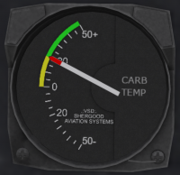
When the temperature shown on the carburetor temperature gauge (Figure 5) is between 0C and 20C (yellow arc), carburetor heat should be applied to prevent icing. Since the carburetor temperature gauge shows the temperature at the intake, the temperature in the carburetor venturi can be lower than at the intake, thus the risk of ice build-up in this range. When the outside temperature is below 0C, then any moisture in the incoming air is already frozen, and thus there is no risk of ice build-up in the carburetor.
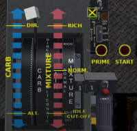
Carburetor heat is controlled through the carburetor air lever (see Figure 6) located on the left side of the engine control quadrant mounted on a console between the pilot and copilot seats. The lever has a white handle on the end and is marked CARBURETOR next to the lever. It is marked DIRECT at the forward end, and ALTERNATE at the aft end of the scale. The lever is used to provide heated air to the carburetor to prevent icing. In the DIRECT position, air is drawn directly through the air intake. As the lever is moved toward the ALTERNATE position, part of the intake air is redirected through a duct heated by the engine exhaust manifold. Use of carburetor heat may require increased throttle due to the lower density of the warm air entering the engine.
Clicking on the engine quadrant will bring up an overlay with scales for the mixture, carburetor heat and the starter and primer buttons. Carburetor air is controlled through the blue scale on the overlay.
