Difference between revisions of "Chinook CH-47/Systems"
(→Emergency Equipment) |
(→Engine Fire Detection System) |
||
| Line 86: | Line 86: | ||
=== Emergency Equipment === | === Emergency Equipment === | ||
| + | |||
| + | [[File:Ch47-fireSystem.png|thumb|right| | ||
| + | <figure id="fig:fireSystem"><caption>Ground Steering Control Panel</caption></figure> | ||
| + | ]] | ||
==== Engine Fire Detection System ==== | ==== Engine Fire Detection System ==== | ||
Revision as of 16:45, 20 June 2021
SECTION 2. SYSTEMS
Contents
1 Helicopter
1.1 General
The Shergood CH-47D is a twin-turbine engine tandem rotor helicopter designed for transportation of cargo, troops and weapons during day, night, visual and instrument conditions. The heicopter is powered by two T550GA-714A shaft-turbine engines on the aft fuselage. Each engine drives a separate engine transmission. Drive shafts from each engine transmission is connected to a shared combining transmission which in turn drives the forward and aft transmissions. The forward transmission is housed in the forward pylon above the cockpit, the combining transmission is housed on the forward side of the aft pylon, and the aft transmission is also housed in the aft pylon behind the combining transmission. When the rotors are not turning, and APU (Auxilary Power Unit) can be used to supply electrical power and hydraulic pressure. Fuel is carried in pods on the sides with main, forward auxilary and aft auxilary tanks on each side. An entrance door is located on the forward right side of the main cabin, while a hydraulically powered ramp is in the back.
1.2 Gross Weight
The maximum gross weight is 50,000 pounds.
1.3 Landing Gear Systems
The landing gear system consists for four non-retractable landing gears mounted on the fuselage pods. The forward gear a fixed with twin wheels. The aft landing gears are single wheels mounted on swivels. In addition, the aft right gear can be steered from the cockput to improve ground handling. Landing Gear Proximity Switches Proximity switches are mounted on each aft landing gear. GROUND CONTACT lights on the maintenance panel in the aft rear of the helicopter indicate when the switches have been activated. While ground contact switches are activated, the trim system will position the forward and aft rotors on GND position for better ground handling.
1.4 Steering and Swivel Lock System
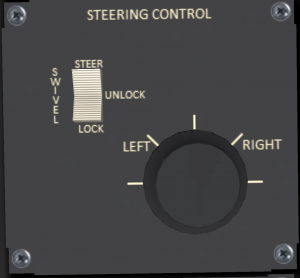
The ground steering control panel (see Figure 1) is located on the center panel between the pilot and co-pilot seats. The ground steering mode is controlled by a three position switch with the following positions:
- STEER - Active steering of the right rear wheel.
- UNLOCK - Free castering of the rear wheels.
- LOCK - Rear wheels locked in straight forward position.
The steering system is powered by the utility hydraulic system. In addition the PWR STEER switch on the upper console must also be in the ON position to use ground steering, or change the active steering mode. When the STEER steering mode is selected, the "keyboard" control mode is active, and the helicopter is in ground contact, the left/right arrow keys that normally control lateral cyclic will switch to controling the wheel position displayed as pedal inputs.
1.5 Parking Brake
A parking brake is located below the lower left corner of the pilot-side instrument panel. Click the parking brake to pull or push the handle. A green "PARK BRAKE ON" capsule will illuminate to indicate the parking brake is engaged. The parking brake requires hydraulic pressure from the utility system, and for the PWR STEER switch to be in the ON position to activate or deactivate. If there is no hydraulic pressure, the parking brake handle can still be pulled or pushed, but the brakes will not engage.
1.6 Pilot-Side Instrument Panel
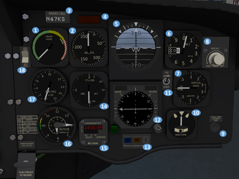
| 1. Cruise Guide Indicator (CGI) | 2. Airspeed Indicator | 3. Radio Call Sign Plate | 4. Master Caution Light |
| 5. Attitude Indicator | 6. Altimeter | 7. Vertical Speed Indicator (VSI) | 8. Radar Altimeter Dimmer Knob |
| 9. Cockpit Air Knob (display only) | 10. Turn and slip indicator | 11. VGI (Vertical Gyro Indicator) mode switch | 12. Horizontal Situation Indicator (HSI) |
| 13. Marker Beacon Lights | 14. Radar Altimeter | 15. Chronometer | 16. Rotor tachometer (RPM) |
| 17. Torquemeter | 18. CGI (Cruise Guide Indicator) test switch |
1.7 Co-Pilot-Side Instrument Panel
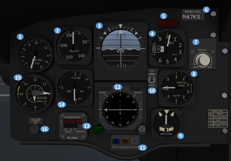
| 1. Torquemeter | 2. Airspeed Indicator | 3. Attitude Indicator | 4. Altimeter |
| 5. Master Caution Light | 6. Radio Call Sign Plate | 7. Radar Altimeter Dimmer Knob | 8. Vertical Speed Indicator (VSI) |
| 9. Turn and slip indicator | 10. VGI (Vertical Gyro Indicator) mode switch | 11. Horizontal Situation Indicator (HSI) | 12. Chronometer |
| 13. Radar Altimeter | 14. Cockpit Air Knob (display only) | 15. Rotor tachometer (RPM) |
1.8 Center Instrument Panel
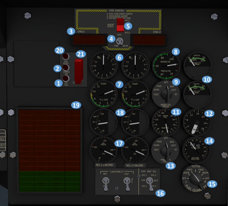
| 1. IFF Failed Indicator Light | 2. Transponder Cypher Active Indicator Light | 3. FIRE PULL handles (Fuel Shut-Off) | 4. Fire Detection Test Switch |
| 5. Agent Discharge Switch | 6. Gas Producer (N1) Tachometer | 7. Power Turbine Inlet Temp. (PTIT) Indicator | 8. Transmission Oil Pressure Indicator |
| 9. Transmission Oil Pressure Selector | 10. Longitudinal Cyclic Trim Indicators | 11. Transmission oil temperature indicator | 12. Fuel flow indicator |
| 13. Transmission oil temperature selector | 14. Fuel quantity indicator | 15. Fuel quantity selector | 16. Caution light and antenna selector |
| 17. Engine Oil Pressure Indicators | 18. Engine Oil Temperator Indicators | 19. Caution/Advisory Panel | 20. GPS Alert Indicator |
| 21. GPS Zeroize Switch |
2 Emergency Equipment
2.1 Engine Fire Detection System
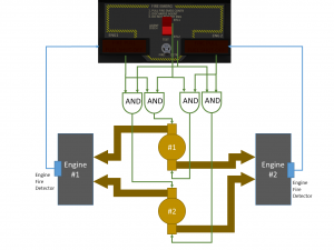
The engine fire detection/extinguisher system is designed to extinguish fires in the engine compartment only. The system (see ) is comprised of two FIRE PULL handles, indicator lights on each handle, an agent discharge switch, a FIRE DETR test switch, and two fire extinguisher agent containers. When a fire is detected in an engine, a light reading "FIRE PULL FUEL SHUT-OFF" will illuminate on the handle for the affected engine. To discharge agent into an engine, first pull the handle to select the engine, then move the AGENT DISCH rocker switch to select a bottle to be discharged. Power is supplied to the fire detection and #1 and #2 extinguisher systems through the #1 and #2 DC buses, respectively.
To perform a system test and check the warning lights, the FIRE DETR switch can be placed in the TEST position. If the system is functioning properly, the "FIRE PULL" indication on both handles will illuminate.
2.2 TROOP WARN Panel
Two troop alarm and jump light boxes are mounted in the rear of the aircraft. The forward box is mounted near the ceiling to the left of the cockpit entrance. The aft box is mounted to the right side of the ramp in the rear of the aircraft. Each box is comprised of an electrical bell and a red and green light fixture on either side. The troop alarm system is controlled through a panel on the overhead switch panel (see ). A three position switch controls which light is illuminated, and a switch turns the bell on or off. Indicator lights on the panel indicate when either light is illuminated.
The troop warning panel can service multiple purposes. It can be used to warn troops to keep clear of APU during engine start, to indicate emergency situations with pretermined signals, or to indicate when the aircraft is over a drop zone.
