EC-135/Police Supplement
Contents
1 Introduction
The police version of the EC-135 seats pilot, copilot, four seated crew members and two "on skid" crew members. One of the crew stations contains controls for the FLIR, Nightsun and CDU (Canister Deployment Unit). Both the FLIR and nightsun are steerable and include a "compass lock" feature to keep them locked to a compass direction. The skid positions include options for standing, sitting (for shooting), and rappelling.
2 Chat Command Summary
The following switches can be controlled through chat commands using the "s" series of switch commands:
Switch Description missionMaster Turns on power to the police operations station. cduPwr Turns on power to the CDU cduArm Arms the CDU for dropping canisters cduArm-g Guard for the arm switch cdu1 - cdu6 Drops canister from each of the slots from #1 to #6.
3 Operator Station
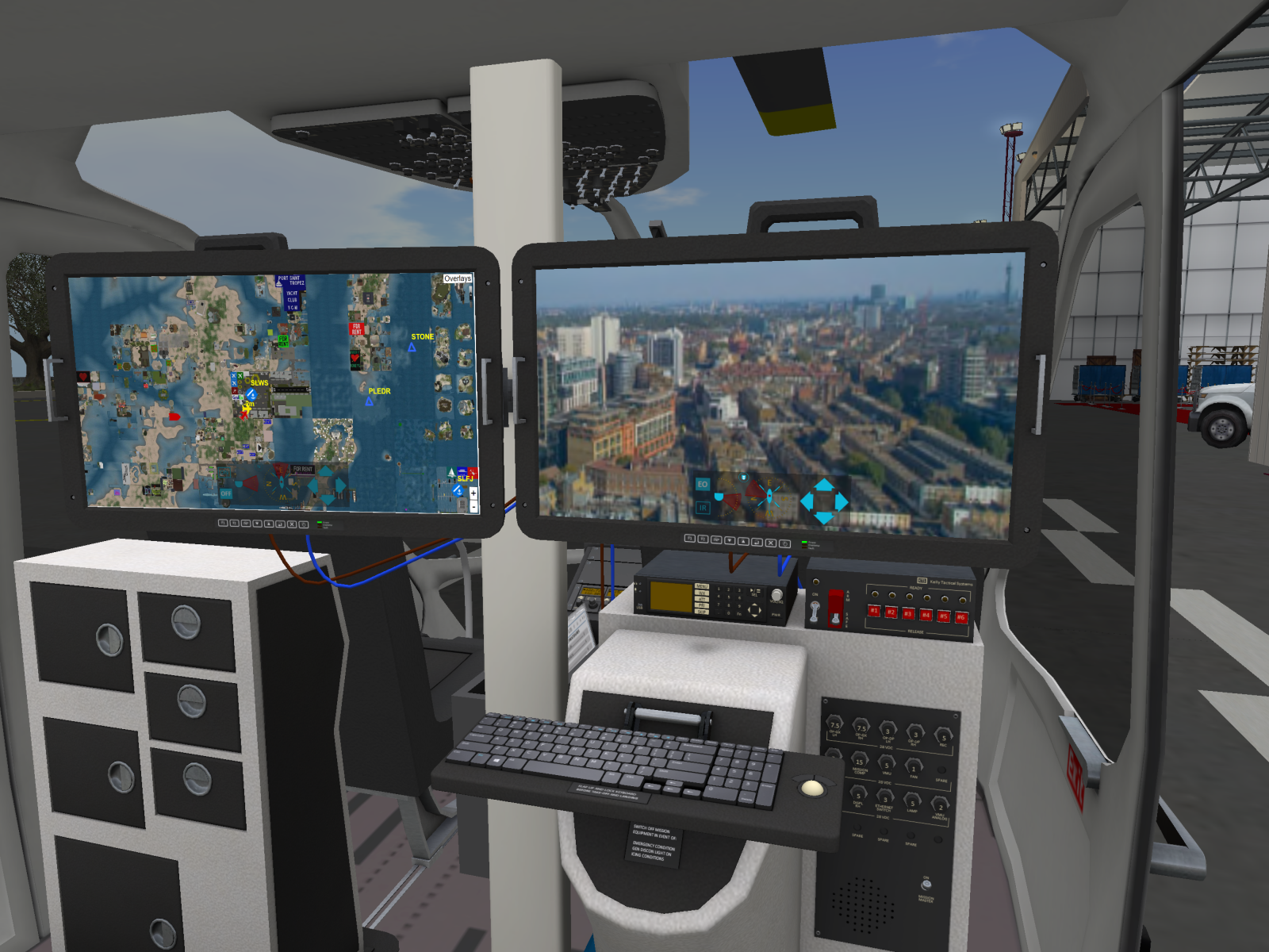
The crew seat behind the pilot is intended for the mission equipment operator. The operator station (see Figure 1) includes two displays (GPS and FLIR), a flip up keyboard, police band transmitter, control unit for the CDU. The keyboard should be flipped up for take-off and landing. Click to flip the keyboard up or down.
The main power switch for the operator station is located on the lower part of the panel below the breakers. The operator station is powered by the #2 Primary Bus and will not function unless this bus is energized. The mission equipment should be powered down in the event of the following conditions:
- Any in-flight emergency condition
- In the event the GEN DISCON light is illuminated in the cockpit
- During icing conditions
4 FLIR
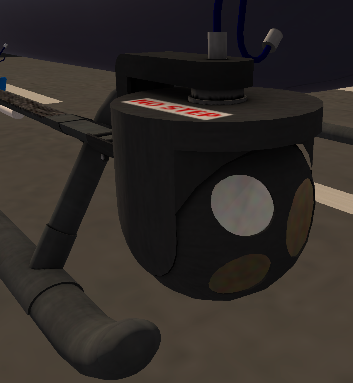
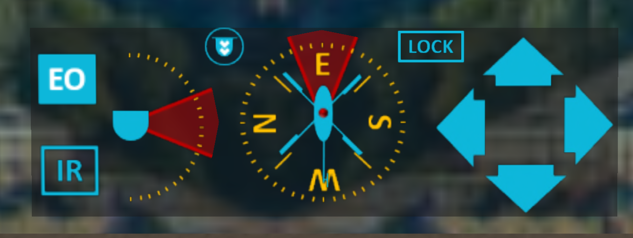
A FLIR (see Figure 2) is mounted on the front of the right skid. The FLIR provides both Infrared (IR) and Electro Optical (EO) imagery which is displayed on the right panel of the operator station. The FLIR is controlled through soft buttons on the on the panel (see figure on right).
The FLIR soft controls (see Figure 3) include the following parts:
- Mode Select -- Buttons labeled EO and IR are located on the left-hand side. These buttons switch between EO (Electro Optical) and IR (Infrared) views on the display.
- Pitch Indicator -- Shows the pitch of the camera relative the the aircraft. The red cone indicates the vertical area covered by the camera.
- Relative and Absolute Direction Indicator -- This indicator consists of an aircraft symbol superimposed over a compass rose. The red cone indicates the current camera direction.
- Compass Lock -- Clicking the lock indicator will activate "compass lock" mode for the camera. In compass lock mode, the camera will maintain the current compass heading, rotating as the aircraft yaws.
- Camera Controls -- Arrow buttons are used to control the camera. Left/Right arrows rotate the camera counter-clockwise and clockwise, respectively. The Up/Down buttons control the pitch of the camera.
5 GPS
The left panel is the GPS display. It is slaved to the pilot GPS, but does not include controls for entering or modifying routes. You can, however, use the zoom controls in the lower right or the filter in the upper right. The operations GPS uses media in the same way as the pilot GPS. Ensure you have media enabled, then click on the panel to display. If the display is not showing correctly, you may need to pause media and click on the screen again.
6 Nightsun
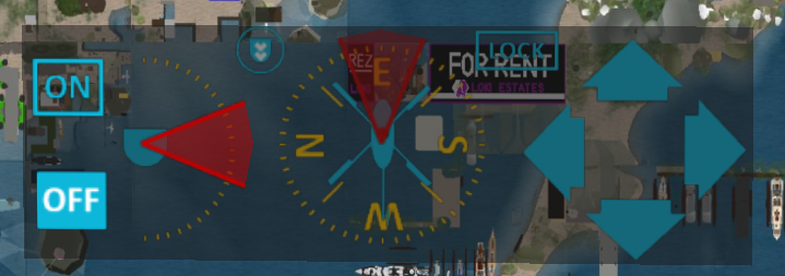
A nightsun is mounted on the front of the left skid. Controls for the nightsun are overlaid as soft buttons on the GPS and are nearly identical to the FLIR camera controls (see Figure 4). The controls include:
- On/Off -- Turns the lamp on or off.
- Pitch Indicator -- Shows the pitch of the nightsun relative the the aircraft. The red cone indicates the vertical area covered by the nightsun.
- Relative and Absolute Direction Indicator -- This indicator consists of an aircraft symbol superimposed over a compass rose. The red cone indicates the current nightsun direction.
- Compass Lock -- Clicking the lock indicator will activate "compass lock" mode for the nightsun. In compass lock mode, the nightsun will maintain the current compass heading, rotating as the aircraft yaws.
- Direction Controls -- Arrow buttons are used to control the direction of the nightsun. Left/Right arrows rotate the nightsun counter-clockwise and clockwise, respectively. The Up/Down buttons control the pitch of the nightsun.
7 CDU (Canister Deployment Unit)
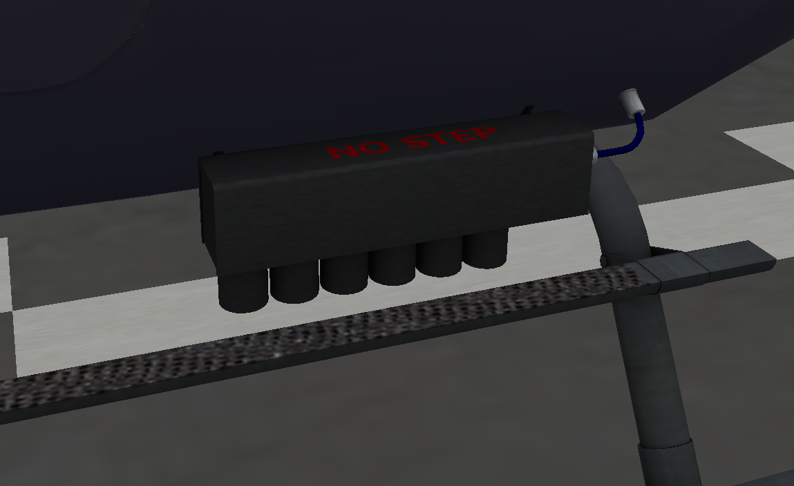
The CDU (see Figure 5) is mounted on the rear of the left skid and contains six slots for anti-riot cannisters. Three types of canisters may be used:
- Smoke Grenades - Thick dark smoke that lasts about 30 seconds.
- Tear Gas - Irritating gas that lasts about 30 seconds.
- Flashbang - Bright flash with loud report
All canisters are fused and will activate 1.5 seconds after release.
7.1 Loading the CDU
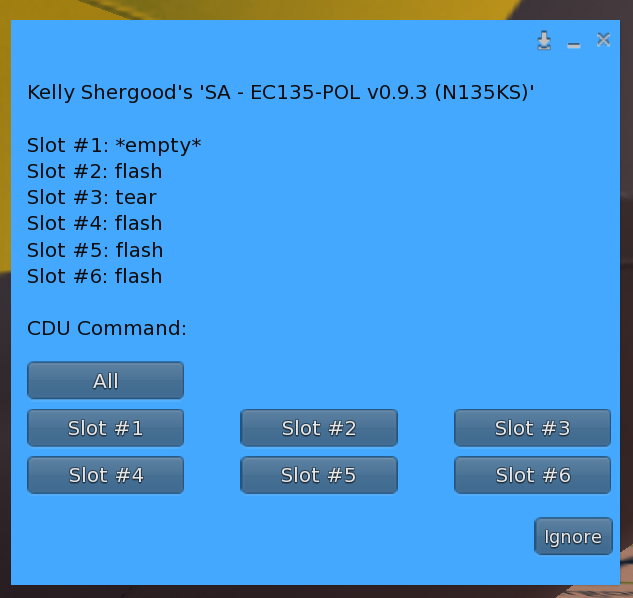
To load or examine the contents of the CDU, click the external unit to get the CDU Main Menu (see Figure 6). The menu will show you the contents of each slot, with buttons to select the contents of all slots or an individual slot. When clicking on a button from the CDU menu, a submenu will appear asking for the ordnance type to load, or "*empty*" to empty that slot. The possible ordinance is determined automatically by scanning the helicopter contents for object names beginning with "grenade:".
7.2 Canister Deployment
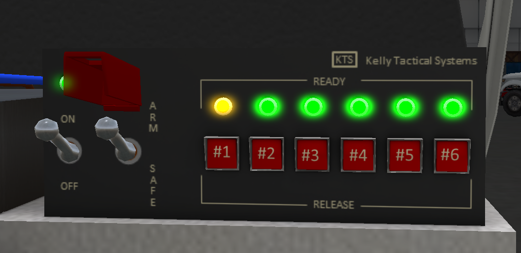
The CDU control panel (see Figure 7) is located on top of the right pedestal of the operator station. The CDU control panel includes a power switch, a guarded ARM switch, and an indicator light and release button for each of the 6 slots.
When power is on, but the unit is not armed, slots loaded with a canister will display in amber, and empty slots will not be illuminated. When power is on and the unit armed, slots with canisters ready for deployment will be illuminated green while all other slots will be amber. Once armed, you can press one of the red buttons to deploy the canister in that slot (or use chat command such as "s cdu2" to release canister in slot #2).
8 Tactical Operations
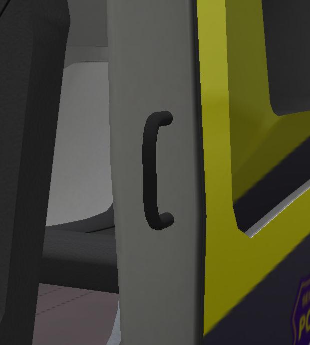
To use the tactical functions of this helicopter, you can "sit" on the black tactical handle in the doorway (see Figure 8). There is a handle located on each side of the helicopter. The sliding door must be open to use this sit location. By default your avi will be positioned standing on the skid. You can toggle between standing on skid, and seated in doorway using the up arrow. While seated, it is possible to use various hand held weapons.
8.1 Rappelling System
Before you can rappel, you must release the rope on the side you want to use. To release a rope, click on either a rope bag (see Figure 9), or on the attachment point on the floor between the seats. This will give you a menu in which you can choose the Right or Left rope. Selecting a rope will toggle the state of the rope (deployed or stowed).
Once a rope is deployed, use the down arrow to begin rappelling. The first down arrow press will move you tot a ready position with feet still on the skid. A second press of the down arrow will begin rappelling just below the skid. Once you are on the rope, use the down arrow to control your descent.
The police EC-135 includes an auto rope length adjustment feature. The helicopter will detect its height above the ground and adjust the rope length accordingly. The rope will also bend based on the attitude of the helicopter so as to always be hanging down.
9 Seat Changes
Avatar in seats other than the pilot and copilot seats can change position by clicking on an unoccupied seat. This includes the tactical positions in the doorway. However, due to SL limitations, your base camera view will be the view for the seat in which you orginially sat.
