S-61R Pelican/Systems
SECTION 2. SYSTEMS
Contents
1 Helicopter
1.1 General
The Shergood S-61R is a twin-turbine engine helicopter designed for transportation of cargo and for search-and-rescue operations in day, night, visual and instrument conditions. The helicopter is powered by two 1,400 shp General Electric T58-GE-10 turbo-shaft engines mounted above the main cabin in front of the main transmission. Drive shafts from each engine is connected to the main transmission through a mixing unit such that the rotors will continue to spin even if one engine fails. When the rotors are not turning, an APU (Auxilary Power Unit) can be used to supply electrical power and hydraulic pressure. Fuel is carried in compartments in the lower hull of the helicopter with forward and aft auxilary and main tanks. An entrance door is located on the forward right side of the main cabin, while a hydraulically powered ramp is in the back. The helicopter is fully amphibious with a "flying boat" style design.
1.2 Gross Weight
The maximum gross weight is 22,050 pounds.
1.3 Pilot-Side Instrument Panel
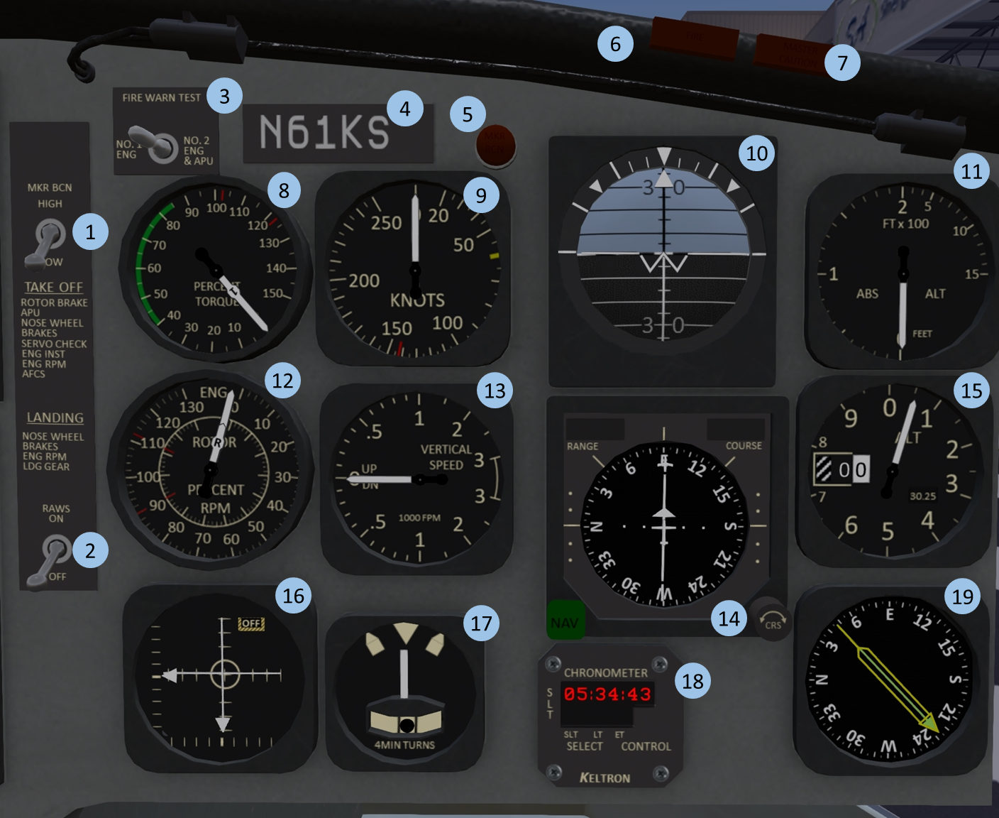
| 1. Marker Beacon Intensity | 2. RAWS Warning | 3. Fire Warning Test | 4. Tail-Number plate |
| 5. Marker Beacon Light | 6. Fire Warning Light | 7. Master Warning Light | 8. Torque Indicator |
| 9. Airspeed Indicator | 10. Attitude Indicator | 11. Radar Altimeter | 12. Tri-Needle RPM |
| 13. Vertical Speed Indicator | 14. HSI | 15. Altimeter | 16. AFCS Indicator |
| 17. Turn/Slip Indicator | 18. Clock | 19. Radio-Magnetic Indicator |
The right portion of the main panel (shown in Figure 1) is intended primarily for use by the pilot sitting in the right-hand seat.
1.4 Co-Pilot-Side Instrument Panel
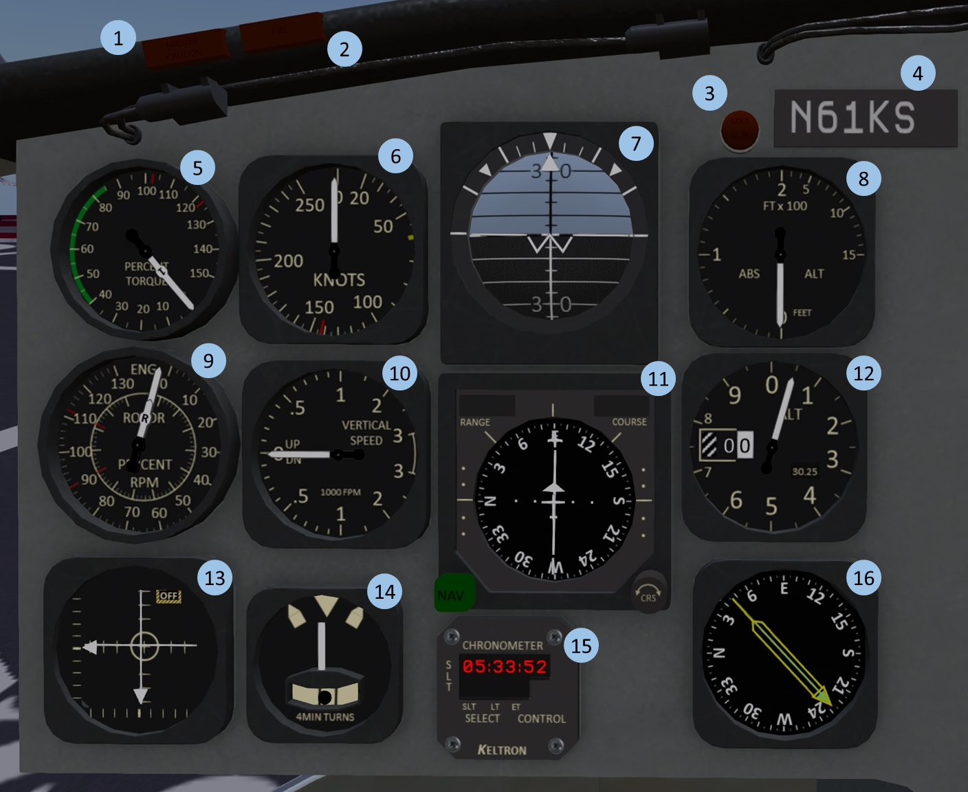
| 1. Master Caution Light | 2. Fire Warning Light | 3. Marker Beacon Light | 4. Tail-Number plate |
| 5. Torque Indicator | 6. Airspeed Indicator | 7. Attitude Indicator | 8. Radar Altimeter |
| 9. Tri-Needle RPM | 10. Vertical Speed Indicator | 11. HSI | 12. Altimeter |
| 13. AFCS Indicator | 14. Turn/Slip Indicator | 15. Clock | 16. Radio-Magnetic Indicator |
The co-pilot side instrument panel is shown in Figure 2.
1.5 Center Instrument Panel
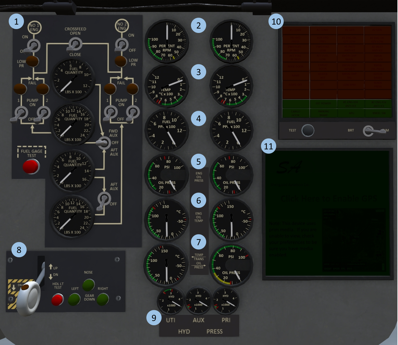
| 1. Fuel Panel | 2. N1 Gauge | 3. Turbine Inlet Temp (TIT) | 4. Fuel Flow |
| 5. Oil Pressure | 6. Oil Temp. | 7. Trans. Temp & Press. | 8. Gear Panel |
| 9. Hydraulic Pressure | 10. Warning/Alert Panel | 11. GPS Moving Map |
1.6 Overhead Panel
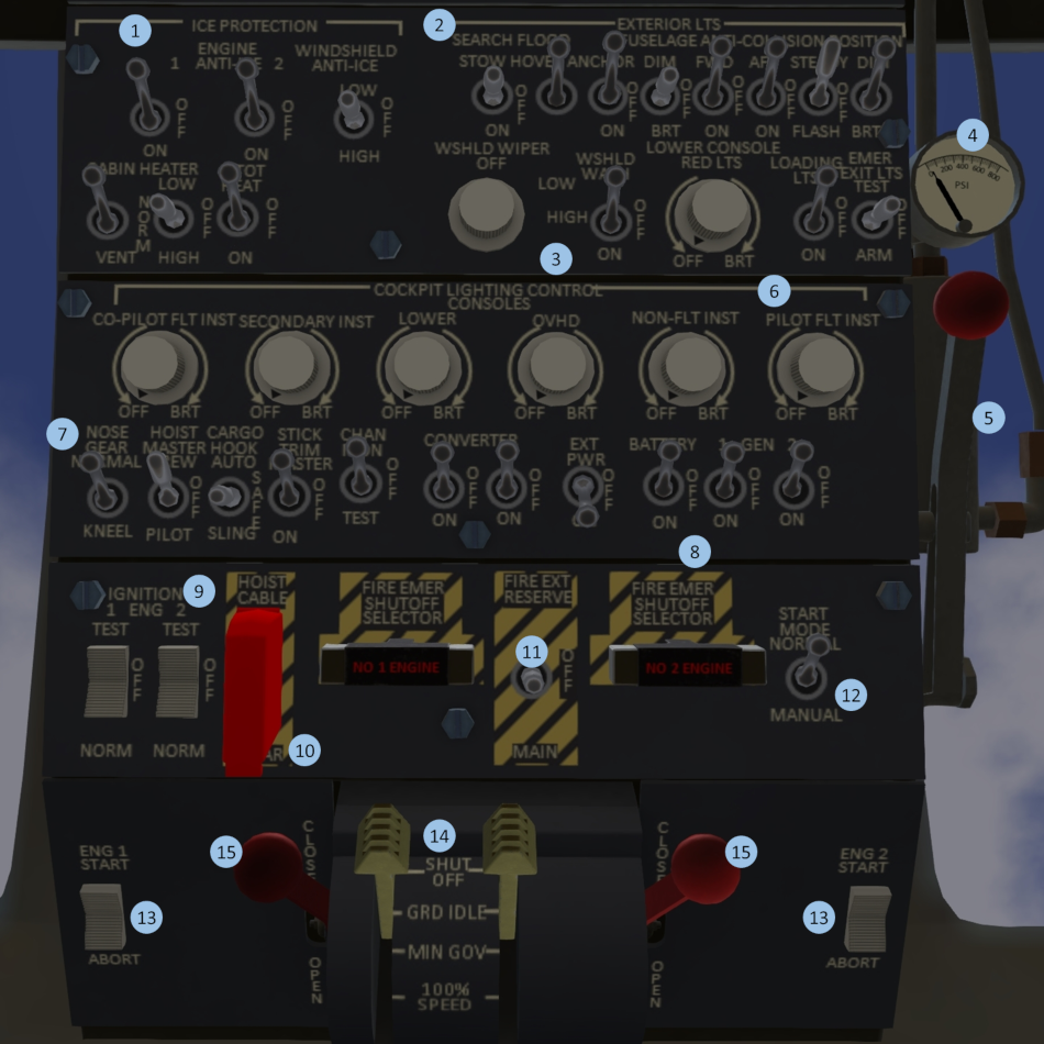
| 1. Ice Protection | 2. Exterior Lighting | 3. Windshield Wiper/Wash | 4. Rotor Brake Press. |
| 5. Rotor Brake | 6. Interior Lighting | 7. System Master Switches | 8. Electrical Systems |
| 9. Ignition | 10. Hoist Cable Shear | 11. Fire Protection | 12. Start Mode |
| 13. Starter | 14. Engine Control | 15. Emergency Throttles |
1.7 Middle Panel
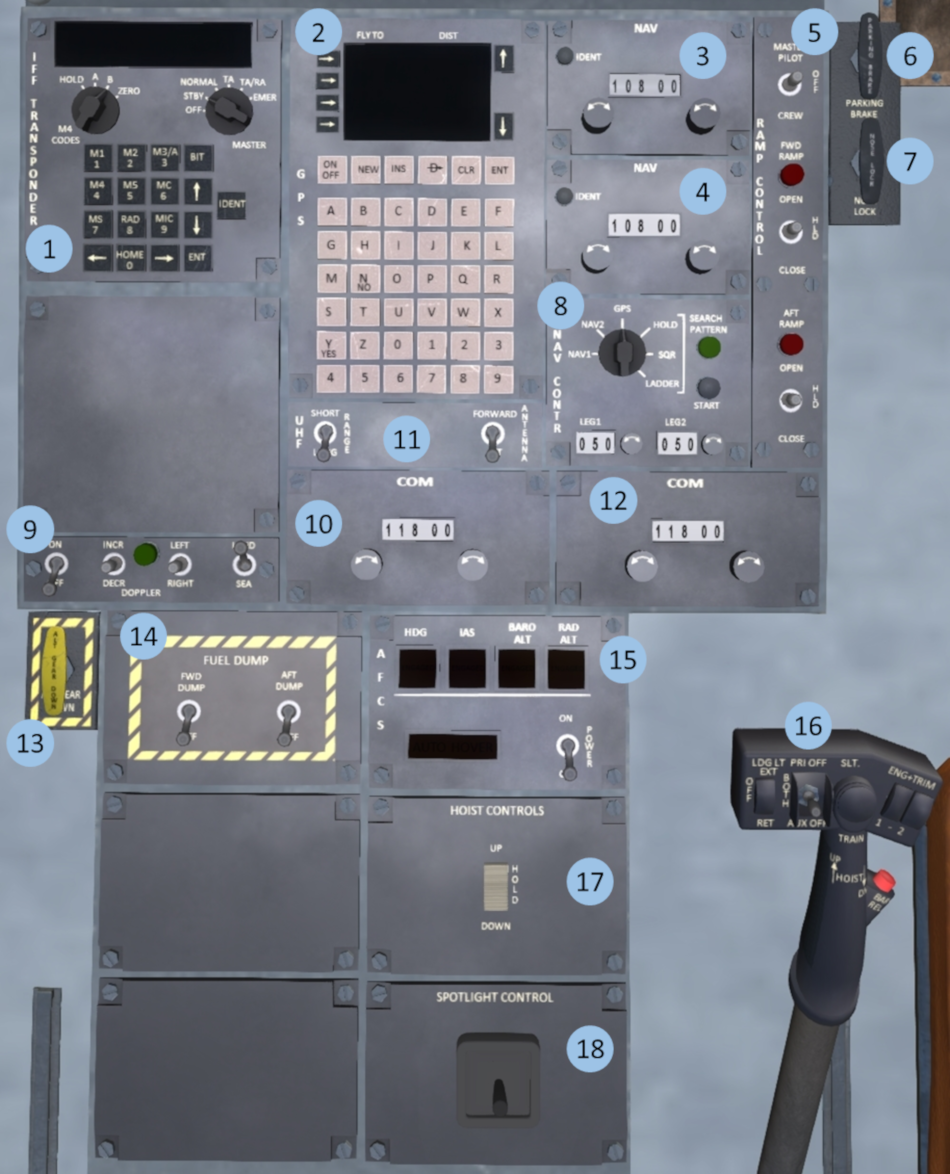
| 1. IFF Trasponder | 2. GPS Panel | 3. #1 NAV Radio | 4. #2 NAV Radio |
| 5. Rear Ramp Control | 6. Parking Brake | 7. Nosewheel Lock | 8. Navigation Control |
| 9. Doppler Panel | 10. Antenna Control | 11. #1 COM Radio | 12. #2 COM Radio |
| 13. Emergency Gear Down | 14. Fuel Dump Panel | 15. AFCS | 16. Hydraulic System Select |
| 17. Hoist Control | 18. Spotlight Control |
1.8 Landing Gear Systems
The S61 has a tricycle type landing gear system with a nosewheel in front and two main gear in sponsons in the back. The gear is hydraulically actuated through the utility hydraulic system. The system includes a squat switch to prevent accidentally raising the gear while the helicopter is on the ground.
1.8.1 Landing Gear Panel
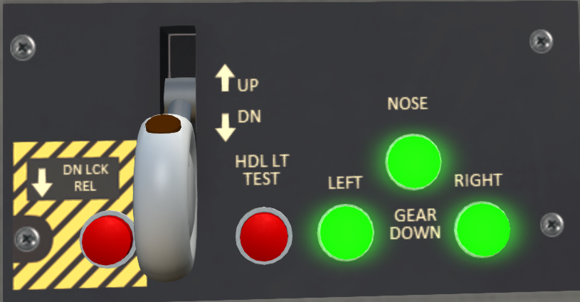
The landing gear panel (see Figure 6) is located on the center portion of the main console. Three lights on the right-hand side of the panel illuminate green when the respective gear is down and locked. The gear is controlled by a two position lever with a red "in motion" indicator light. The light illuminate when the landing gear are in motion. A test button labeled "HLD LT TEST" can be pressed to test the "in motion" indicator light. Finally, a DN LCK REL button can be used to override the squat switch allowing gear to be raised while on the ground.
1.8.2 Landing Gear Malfunctions
Normal wear and tear, or damage through a hard landing can cause the landing gear to malfunctions. Malfunctions may affect retracting, lowering or both. When changing the gear position always verify the red "in-motion" light on the handle comes on, then goes out several seconds later. When lowering gear, always verify you get three green lights indicating the gear is down and locked.
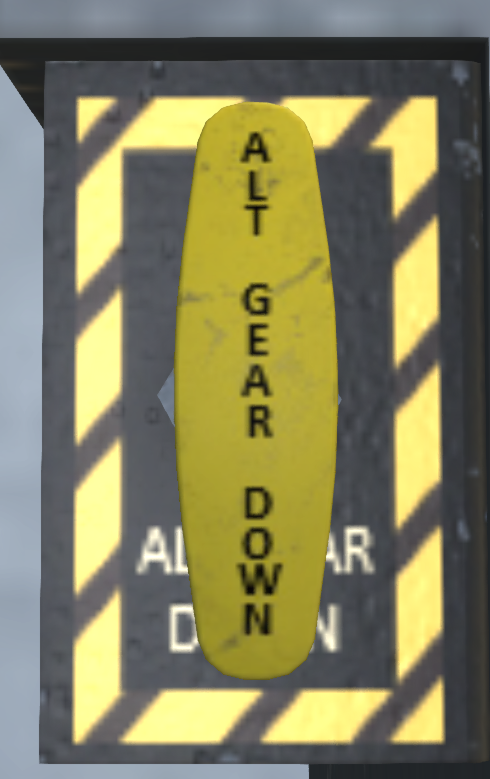
In the event that the gear fails to retract, travel to the next point of landing can be continued, but caution should be used to keep the landing as soft as possible. In the event that gear fails to lower, there is an emergency gear handle (see Figure 7) on the copilot side of the middle console. This handle deploys a compressed air bottle to force the gear into the down position. After use, the air bottle must be replaced before it can be used again. Once the emergency gear extension system is activated, the gear is prevented from retracting until repairs are made to the gear system.
1.8.3 Kneel System
A nose gear kneel switch (see Figure 8) is located on the upper console. This switch is only effective when the landing gear handle is in the down position. Flipping this switch will cause the nose wheel to retract to a 50% retracted position. This can be used to increase the clearance under the tail for loading the helicopter through the ramp. Like the landing gear system, the kneel system requires utility hydraulic pressure to operate.
1.9 Parking Brake
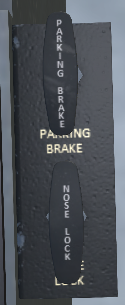
A parking brake (see Figure 9) is located on the pilot side of the middle console. Activating the parking brake will increase resistance to ground movement. Click the handle to toggle its position, or use the chat command:
s brake
to toggle it.
1.10 Nose Wheel Lock
A nosewheel lock (see Figure 9) is located on the pilot side of the middle console just below the parking brake. Activating the parking brake will increase resistance to rotation while on the ground. Click the handle to toggle its position, or use the chat command:
s noselock
to toggle it. The nosewheel lock should be used during rotor engagement to prevent the helicopter from turning on the ground during the high-torque stages of engagement.
2 Emergency Equipment
2.1 Engine Fire Detection System
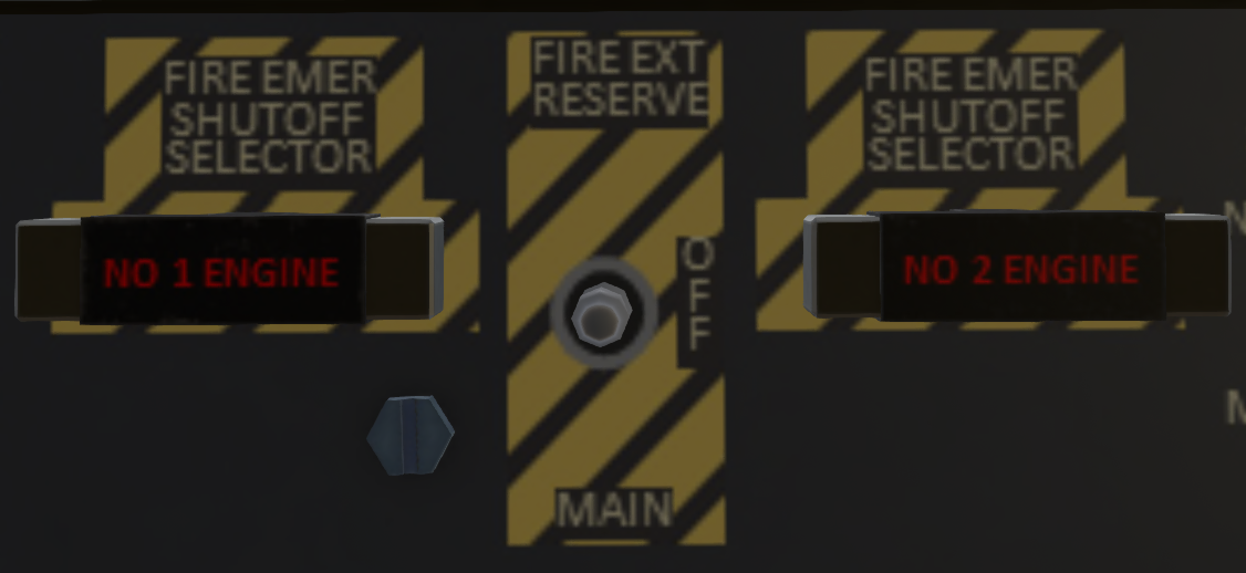
The S61 is equipped with fire sensors and two fire extinguisher bottles to detect and mitigate engine fires. The fire detection system for the #1 and #2 engines is power by the #1 and #2 AC bus, respectively. The fire detection panel is located on the upper console behind the throttle quadrant (see Figure 10). The panel has two fuel cut-off handles for each engine. The handles will light up when a fire is detected (if AC power is available). Pulling a handle will cut off fuel to an engine through a mechanical linkage.
The fire extinguishers are activate by a 3-position toggle switch between the fuel cut-off handles. The switch will have no effect except when a handle is pulled. This switch should normally be left in the middle OFF position. When deploying an extinguisher, first pull the cut-off handle for the affected engine, then switch the FIRE EXT switch to MAIN. This will deploy the bottle corresponding to the affected engine (#1 bottle for #1 engine, #2 bottle for #2 engine). If a single bottle is insufficient to extinguish a fire, you can switch the FIRE EXT switch to the RESERVE position. This will deploy the bottle from the opposite engine (#2 bottle for #1 engine, or #1 bottle for #2 engine). The fire extinguisher bottles are single use. Once they have been used, they must be replaced on the ground.
2.2 APU Fire Detection System
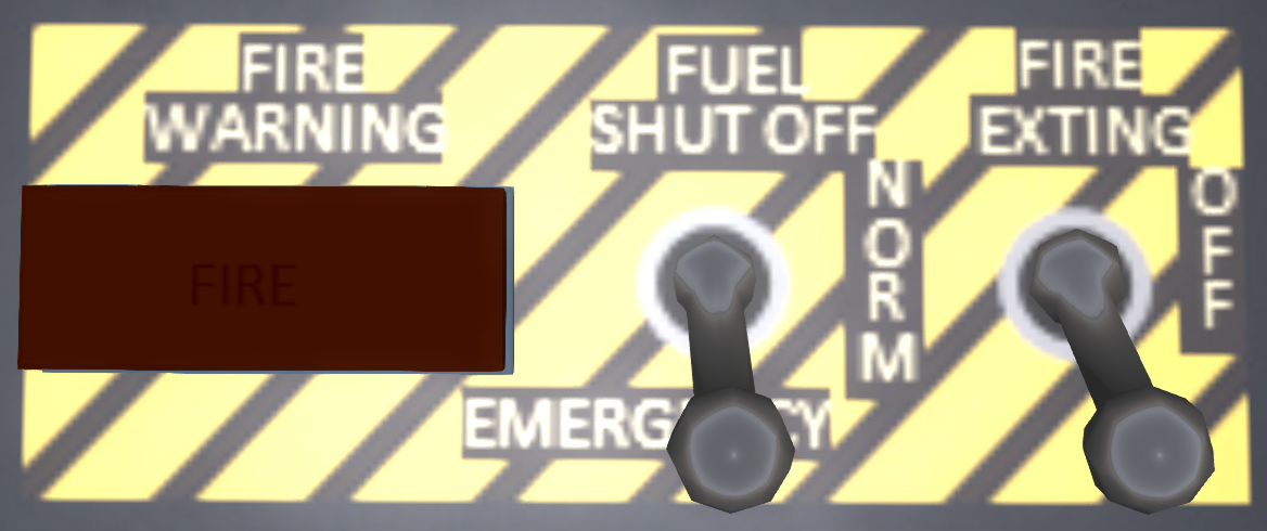
The APU fire detection panel (see Figure 11) is on the APU panel located on the pilot's side panel. The APU fire detection and mitigation system operates off the DC bus. A warning light will illuminate to indicate a fire has been detected. To activate the fire suppression system, flip the FUEL SHUT OFF switch and FIRE EXTING switches to the forward position.
2.3 Fire Warning Test Panel
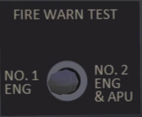
A fire warning test panel is located on the pilot side of the main panel (see Figure 12). The panel contains a three-position switch. Flipping the switch to either side from the center position will test the fire detection system and lights for the indicated systems. When the switch is moved to the left marked NO 1 ENG, the fire detection warning light in the Engine #1 fuel cut-off handle will illuminate. When the switch is moved to the right marked NO 2 ENG & APU, the fire detection warning light in the Engine #2 fuel cut-off handle will illuminate, as well as the warning light for the APU.
2.4 Emergency Lights
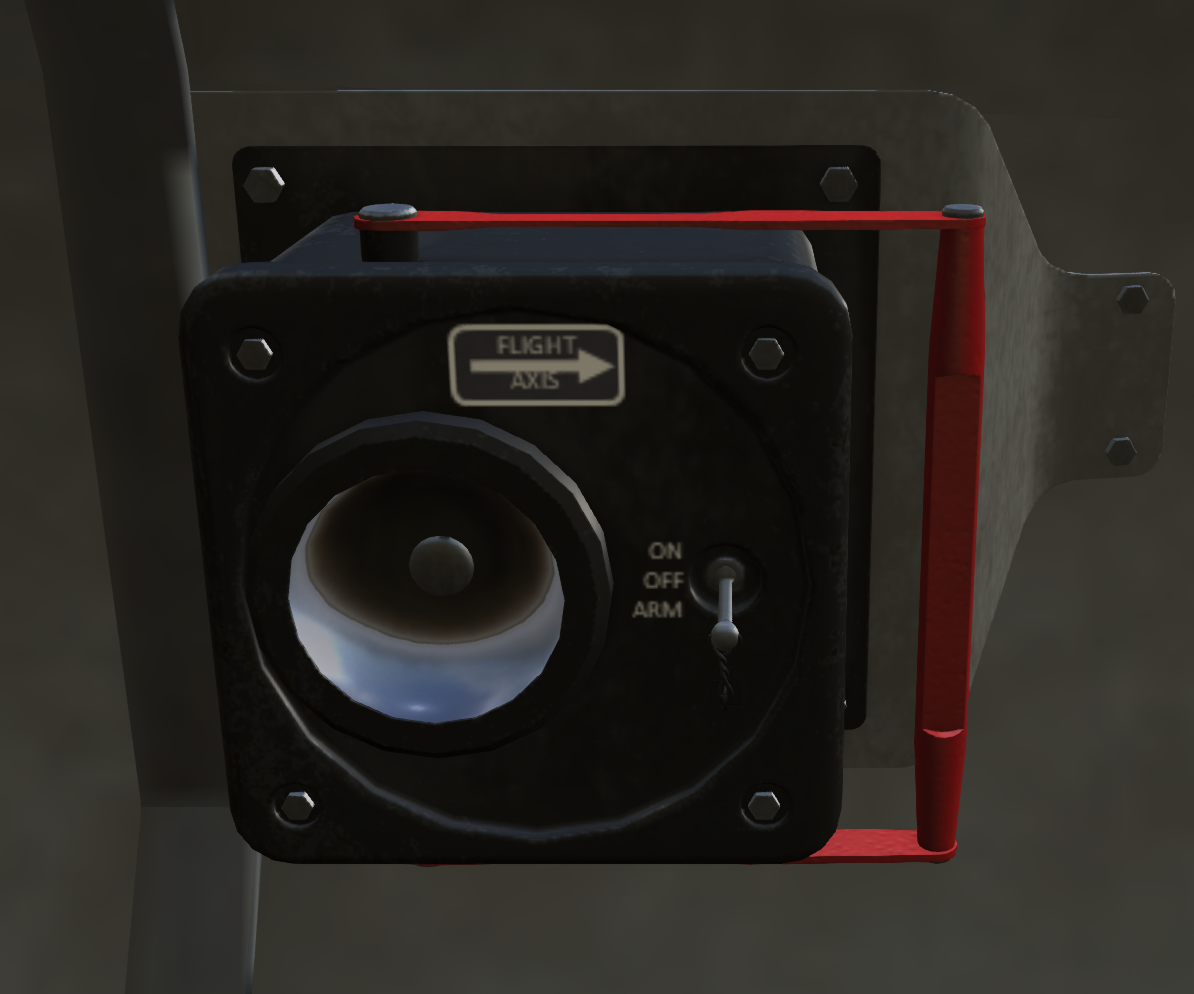
Emergency lights (see Figure 13) are installed at various positions in the helicopter and provide lights for emergency evacuation in the event of a crash. They are controlled by a three position switch labeled EMER EXIT LIGHTS on the pilot-side of the upper console. In the TEST position, all emergency lights will turn on for testing. In the OFF position, the lights will always remain OFF. In the ARM position (recommended for normal flight), the emergency lights will come on in the event of a sudden acceleration or shock. Once the shock sensor has been tripped, it must be manually reset by clicking on one of the emergency lights in the helicopter.
2.5 Emergency Ramp Release
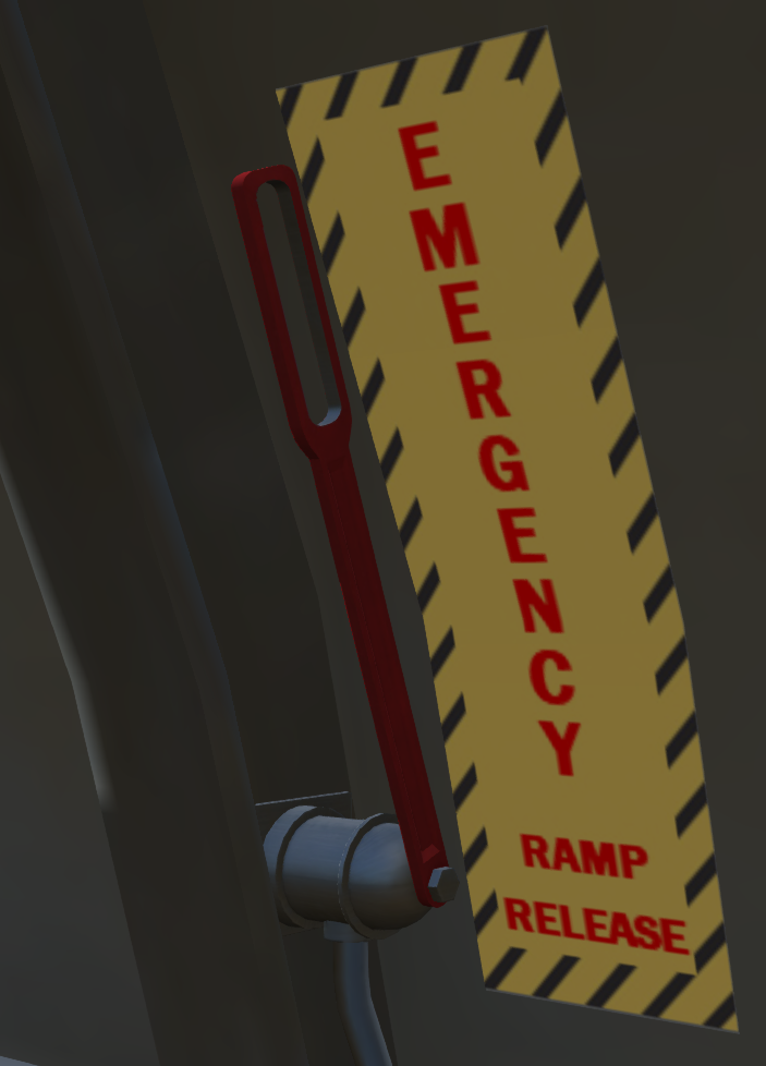
An emergency ramp release (see Figure 14) is located in the rear of the aircraft on the right side near the ramp. Pulling this lever will disconnect the ramp from the hydraulic actuators and allow it to fall by gravity. Click the lever again to reengage the hydraulic actuators and restore normal functioning to the ramp.
3 Engines and Related Systems
3.1 General
The S61-R is powered by two General Electric T58-GE-10 turboshaft engines delivering 1,400 shp each. The engines are mounted above the main cabin in front of the main transmission.
