Steamly S2-S/Systems
SECTION 2. SYSTEMS
Contents
1 Helicopter
1.1 General
The Shergood Steamly S2-S is a single-engine steam-turbine powered helicopter. It employs a closed-loop steam system consisting of a boiler, a steam turbine, a condenser and a water reservoir. A fuel oil burner in the boiler provides the heat to produce steam which is then directed into the turbine through the throttle valve. Steam exiting the turbine is passed through a condenser with twin engine powered cooling fans.
1.2 Gross Weight
The maximum gross weight is 2,100 pounds.
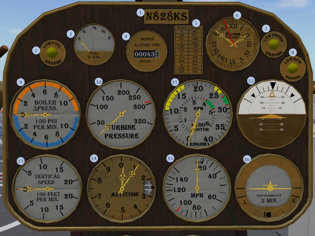
1.3 Main Instrument Panel
| 1. Tail-Number plate | 2. Low Fuel Warning Light | 3. Fuel Indicator | 4. HOBBS Time |
| 5. Compass Card | 6. Clock | 7. Low Boiler Pressure Warning Light | 8. Low RPM Warning Light |
| 9. Boiler Pressure Differential Indicator | 10. Turbine Pressure Indicator | 11. Engine/Rotor RPM Indicator | 12. Attitude Indicator |
| 13. Vertical Speed Indicator | 14. Altimeter | 15.Airspeed Indicator | 16. Turn and Bank Indicator |
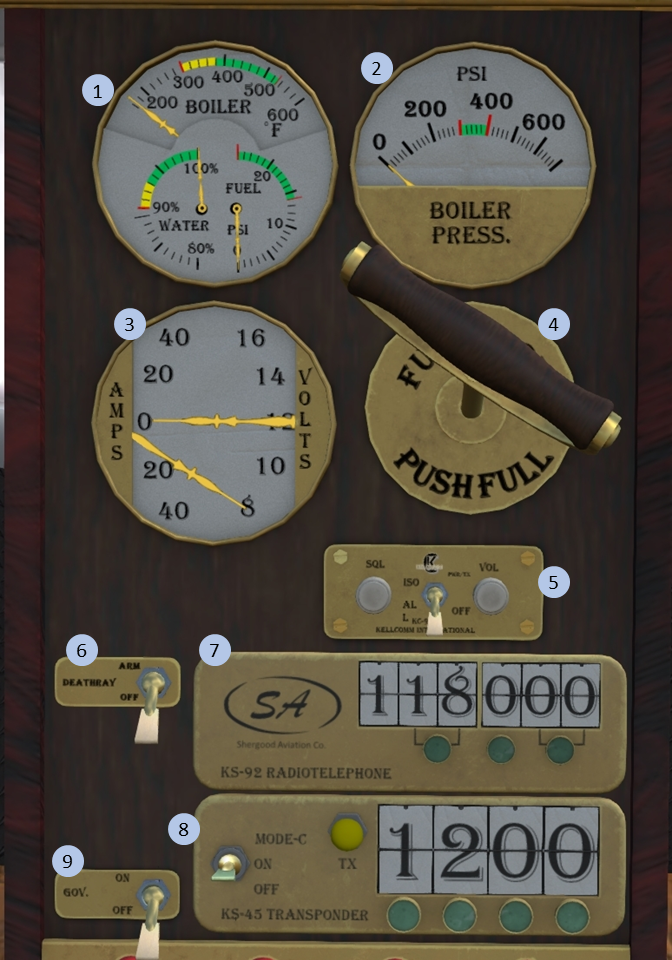
1.4 Mid Instrument Panel
|
Figure 2: Mid instrument panel
|
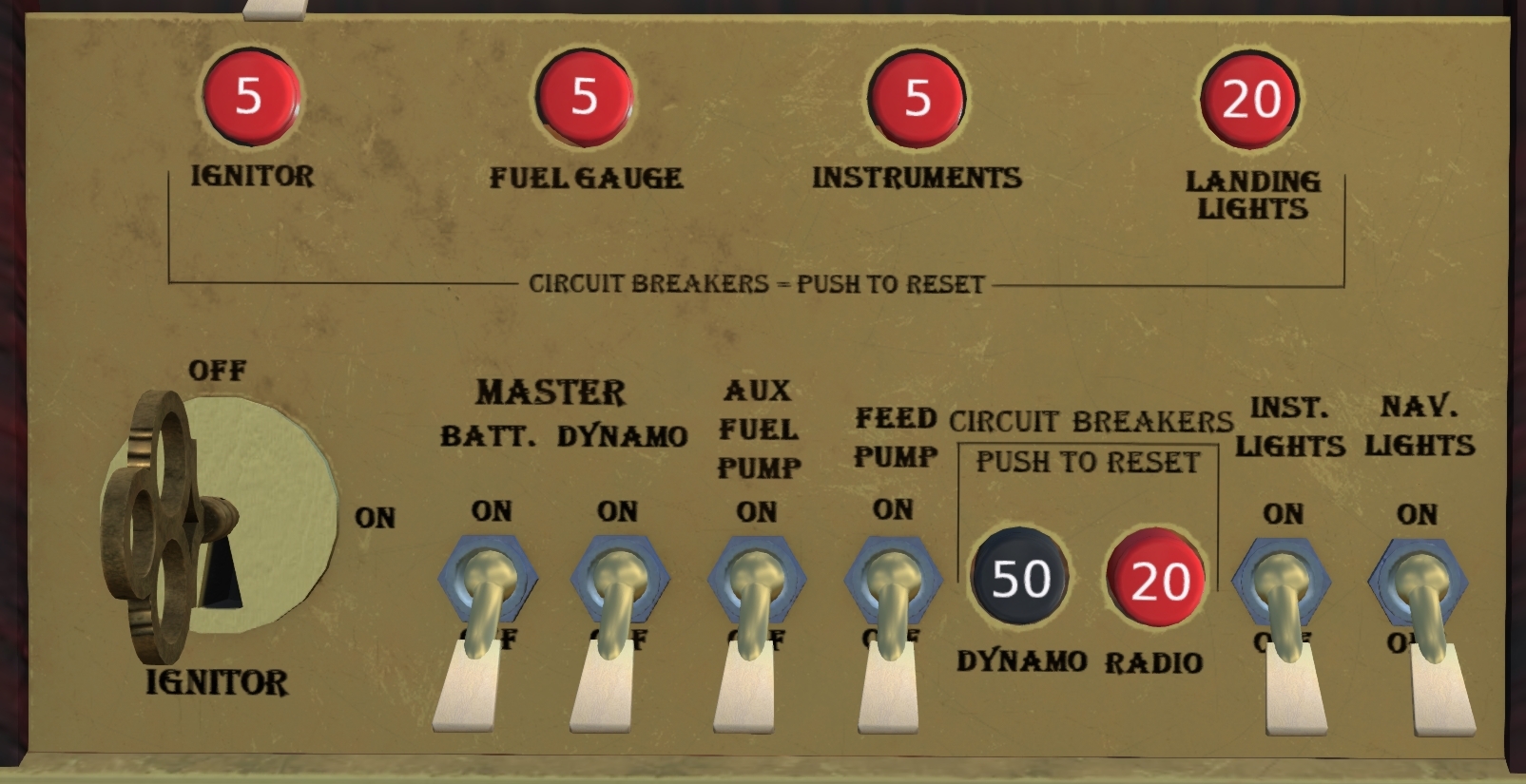
1.5 Switch Panel
A switch panel is located at the bottom of the instrument panel and contains the majority of the switches and breakers in the aircraft. Left to right the switches are:
- Ignitor - Key switch that turns on the ignitors for the burner. Requires that electrical power be active as well.
- Batt. (Master) - Main electrical power from the battery.
- Dynamo (Master) - Main electrical power from the dynamo. The dynamo is powered when the engine RPM is at least 50%.
- Aux Fuel Pump - Provides fuel pressure to the burner via an electrically driven pump
- Feed Pump - Pumps water from the reservoir to the boiler.
- Inst. Lights - Provides light for the cabin from two lights mounted on the back wall.
- Nav. Lights - Powers the three navigation lights, right on the left, blue-green on the right and white on the tail.
1.6 Magnetic Compass
A magnetic compass (Figure 4) is mounted on top of the main instrument panel. Note that the magnetic compass is only accurate in straight and level flight and is subject to the following types of error:
- Oscillation - Turbulence and motion of the aircraft will cause the compass reading to oscillate. The more steady the aircraft is held in a level attitude, the more accurate the reading will be.
- Deviation - Magnetic fields generated by the aircraft itself can affect the compass reading. A compass card (Figure 1 (#5)) on the main panel provides corrections from indicated headings to actual headings.
- Turning Error - Magnetic dip causes the compass to produce erroneous readings while in a turn on certain headings. These errors are most pronounced near North and South headings. While close to a North heading, the compass heading shown will tend to undershoot the actual heading, and while close to a South heading the heading shown will tend to overshoot the actual heading. When on an East or West heading, this error will be negligible. You can use the acronym UNOS (Undershoot North, Overshoot South) to remember direction of the error.
1.7 Beacon
A flashing beacon is mounted on the belly of the aircraft. The beacon is activated through a switch (Figure 5) mounted under the pilot seat.
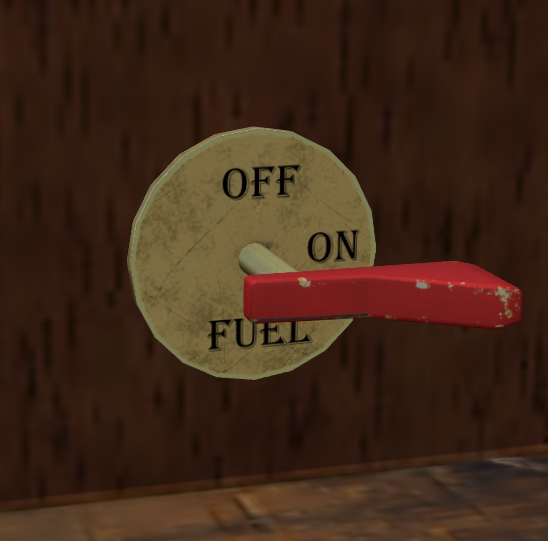
1.8 Fuel Cutoff
A red fuel cut-off lever (Figure 6) is mounted under the pilot seat. Fuel flow to the burner is on when the lever is in the horizontal position.
1.9 Rotor Brake
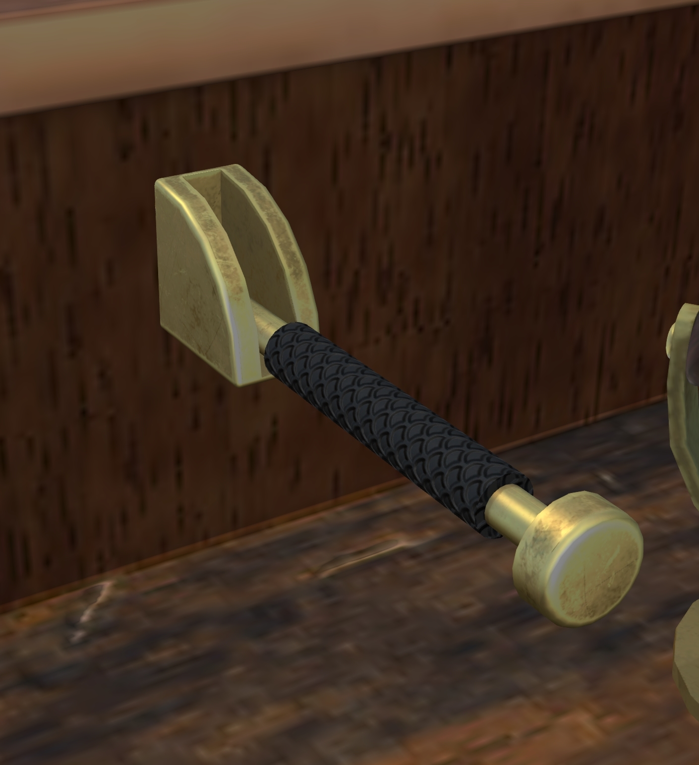
A rotor brake lever (Figure 7) is mounted under the pilot seat. The rotor brake is on when the lever is in the up position.
1.10 Steam Whistle
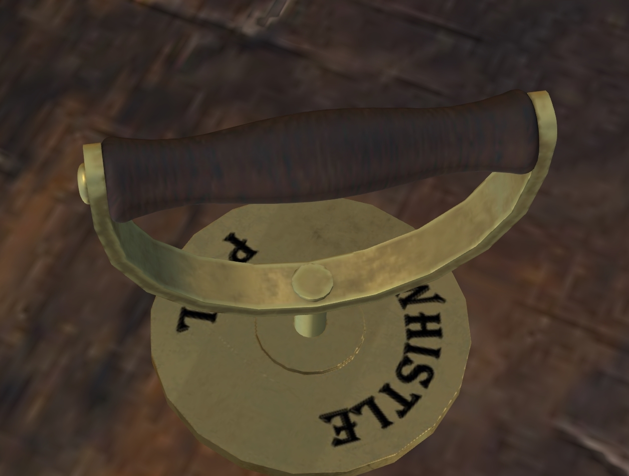
A handle (Figure 8) on the floor of the cockpit is used to activate the steam whistle through a cable and pulley system. The whistle will operated when the handle is in the up position. The whistle can be used as an audible signal to nearby personal on the ground, or to assist in reliving excess pressure in the boiler.
2 Rotor and Power Train System
The rotor configuration of this helicopter consists of a single main lifting rotor system and an anti-torque tail rotor system. Both systems are driven by the engine through the transmission system and are controlled by the flight control system.
2.1 Main Rotor System
The main rotor system consists of the main rotor hub and three main rotor blades. Each should be inspected separately during the pre-flight inspection. The main rotor is controlled through a swash plate and control linkages connected to the collective and cyclic controls in the cockpit.
2.2 Tail Rotor System
The tail rotor is mounted on the right side of the vertical stabilizer. It acts to counteract torque from the main rotor and provide yaw control of the aircraft in a hover, and coordination for turns at cruise speed. The tail rotor is controlled through anti-torque pedals in the cockpit that alter the pitch of the blades thus increasing or decreasing the tail-rotor thrust.
2.3 Main Transmission
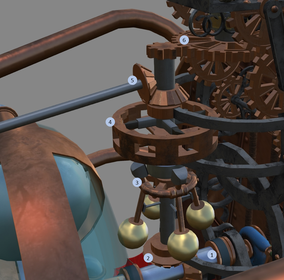
The main transmission (Figure 9) translates power from the engine to the rotor system. Rotational power is supplied through the main drive shaft (#1) from the steam turbine. A bevel gear (#2) translates the horizontal rotation from the main drive shaft to a vertical input shaft to the transmission. The transmission includes a centrifugal clutch (#3) and a sprag clutch (#4), an additional bevel tap gear (#5) for the tail rotor drive shaft, and finally a reduction gear (#6) to reduce the RPM from engine to the RPM for the main rotor.
2.3.1 Centrifugal Clutch
The centrifugal clutch (Figure 9, element #3) serves to decouple the rotor system from the engine during startup. It consists of four weighted balls mounted on hinges around a ring with friction pads attached to each weight through a lever. As the engine RPM increases, centrifugal force will pull the balls outward. When the centrifugal force is strong enough, the friction pads will contact the middle vertical drive shaft transferring the power from the engine.
2.3.2 Sprag (Freewheeling) Clutch
A sprag clutch (Figure 9, element #4) connects the middle vertical drive shaft to the upper vertical drive shaft. It consists of lower section with four spring-loaded teeth driven by the middle vertical drive shaft that interact with a ratchet gear driving the upper vertical drive shaft. This arrangement allows the main rotor to "freewheel" in the event power from the engine is lost.
3 Landing Gear
The S2-S has a fixed skid-type landing gear system with left and right skids mounted on shock absorbing pivots.
4 Engine and Related Systems
The S2-S is powered by a 200 HP steam turbine engine with a closed-loop system (Figure 10). A boiler provides steam pressure which is feed to a steam turbine through a throttle valve. Steam from the turbine passes through a condenser to a water reservoir, which is then pumped back to the boiler via a feed pump. Each of the components are described in further detail in the following sections.
4.1 Boiler
The main source of steam for the S2-S is a boiler is mounted in the rear of the engine compartment. The boiler consists of three sections, a firebox, a smokebox and the main boiler compartment. The firebox takes up the portion of the boiler on the right side of the aircraft and contains a burner fed by a fuel-oil line, and an ignitor to begin combustion at start-up. While once the burner has started, the ignitor is no longer needed to maintain the flames, it is recommended that the ignitor be left on to facilitate reignition in the event the flame is extinguished.
The smokebox on the left side of the aircraft collects the hot gasses from burner and channels them to the smokestack. A set of tubes passing through the main boiler chamber connects the firebox with the smokebox. It is important that the tubes remain submerged in water while the boiler is operating. The water level should never be allowed to fall below 90% capacity while operating.
Under normal operation, the pressure in the boiler chamber should be maintained between 300 and 400 psi. This pressure acts as an energy reservoir which can be directed to act on the turbine through a throttle valve. If the boiler pressure is allowed to fall bellow 300 psi, then there will be insufficient pressure to produce full power which can result in loss of rotor RPM when high power is demanded of the engine. Excessive boiler pressure, on the other hand, can lead to failure of the boiler pressure vessel and subsequent loss of the aircraft.
4.1.1 Vent Valve
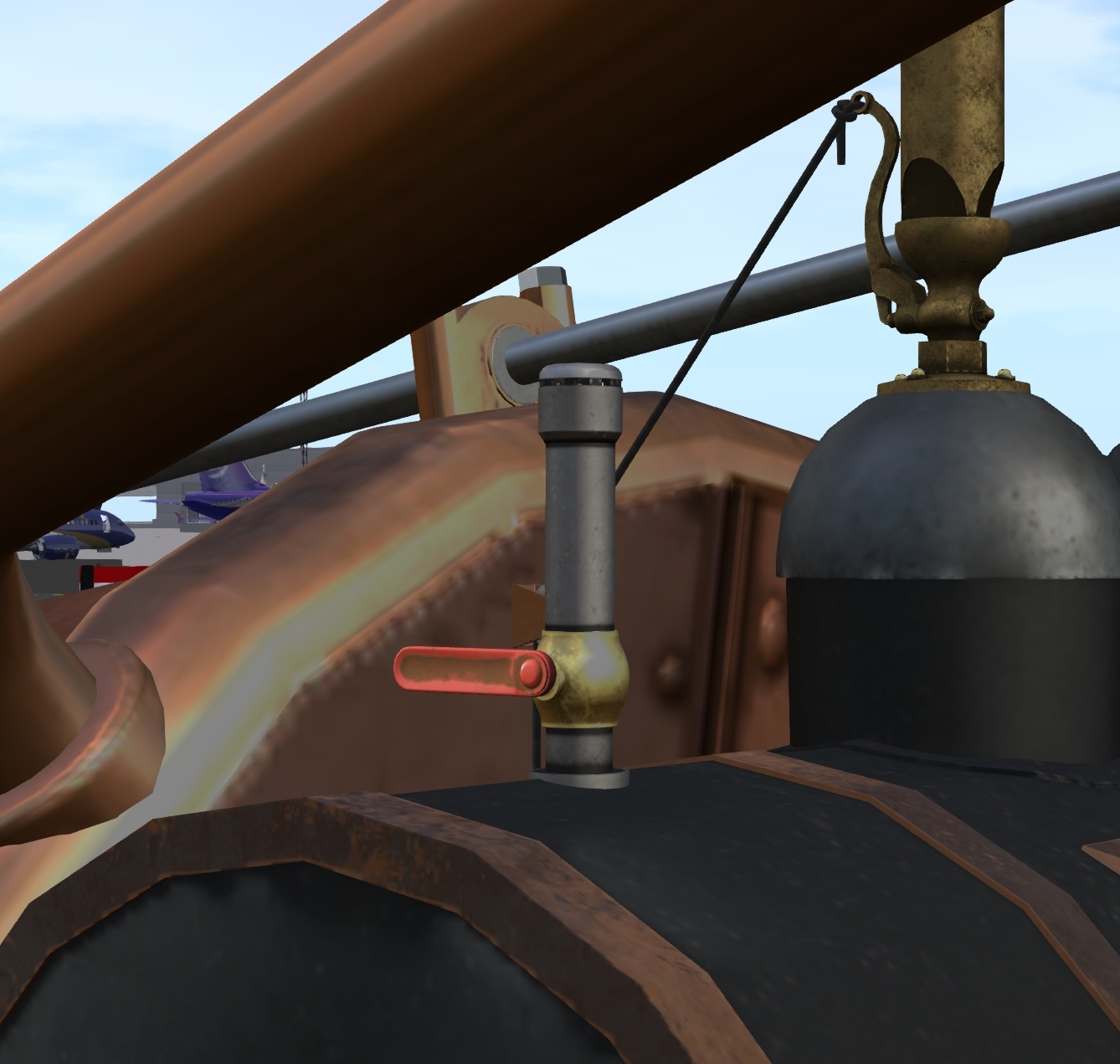
A vent valve (Figure 11) is located on the of the boiler vessel. This valve is used during startup to vent air from the boiler chamber to ensure that the chamber contains only steam during operation. Failure to vent the air from the boiler before operation will increase the temperature needed to achieve operating pressure and reduce the efficiency of the boiler.
4.1.2 Steam Whistle
A steam whistle that can be operated via a cable and pulley system is mounted on top of the boiler. When active, steam from the boiler is allowed to escape through the whistle. Extended use of the whistle will reduce pressure in the boiler over time, unless fuel flow is increased at the burner. For this reason, its use in flight is discouraged when pressure is below 300 psi. Conversely, opening the whistle in addition to reducing fuel flow can be used to more quickly reduce boiler pressure when the 400 psi limit has been exceeded.
