Steamly S2-S/Systems
SECTION 2. SYSTEMS
Contents
1 Helicopter
1.1 General
The Shergood Steamly S2-S is a single-engine steam-turbine powered helicopter. It employs a closed-loop steam system consisting of a boiler, a steam turbine, a condenser and a water reservoir. A fuel oil burner in the boiler provides the heat to produce steam which is then directed into the turbine through the throttle valve. Steam exiting the turbine is passed through a condenser with twin engine powered cooling fans.
1.2 Gross Weight
The maximum gross weight is 2,100 pounds.
1.3 Main Instrument Panel
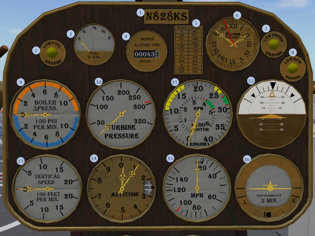
Figure 1: Main instrument panel
| 1. Tail-Number plate | 2. Low Fuel Warning Light | 3. Fuel Indicator | 4. HOBBS Time |
| 5. Compass Card | 6. Clock | 7. Low Boiler Pressure Warning Light | 8. Low RPM Warning Light |
| 9. Boiler Pressure Differential Indicator | 10. Turbine Pressure Indicator | 11. Engine/Rotor RPM Indicator | 12. Attitude Indicator |
| 13. Vertical Speed Indicator | 14. Altimeter | 15.Airspeed Indicator | 16. Turn and Bank Indicator |
1.4 Mid Instrument Panel
|
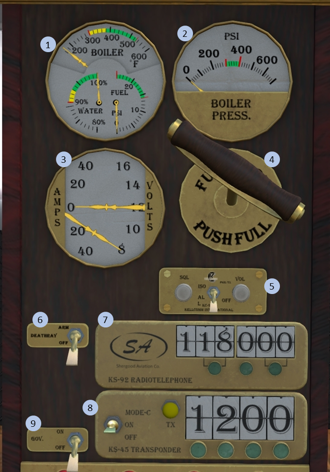
Figure 2: Mid instrument panel
|
1.5 Switch Panel
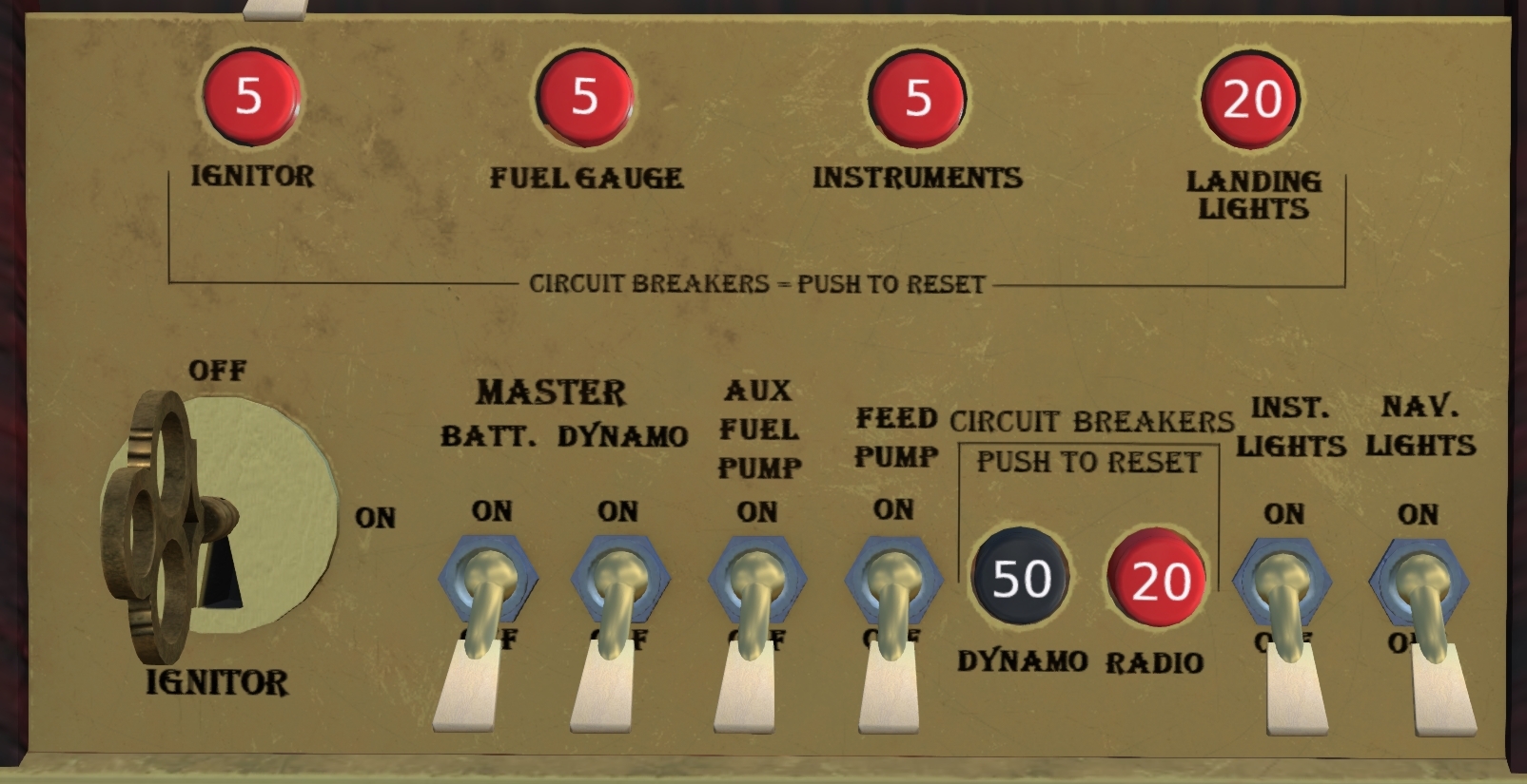
A switch panel is located at the bottom of the instrument panel and contains the majority of the switches and breakers in the aircraft. Left to right the switches are:
- Ignitor - Key switch that turns on the ignitors for the burner. Requires that electrical power be active as well.
- Batt. (Master) - Main electrical power from the battery.
- Dynamo (Master) - Main electrical power from the dynamo. The dynamo is powered when the engine RPM is at least 50%.
- Aux Fuel Pump - Provides fuel pressure to the burner via an electrically driven pump
- Feed Pump - Pumps water from the reservoir to the boiler.
- Inst. Lights - Provides light for the cabin from two lights mounted on the back wall.
- Nav. Lights - Powers the three navigation lights, right on the left, blue-green on the right and white on the tail.
The breakers on the switch panel are:
- Ignitor - Protects the ignitor circuit from overload.
- Fuel Gauge -
- Instruments -
- Landing Lights -
- Dynamo -
- Radio -


