Chinook CH-47/Servicing
SECTION 9. SERVICING
Contents
1 GENERAL
This section describes fluid (other than fuel) and servicing/repair procedures. Fueling procedures can be found in Section 2 - Systems (Fuel Systems).
2 ENGINES
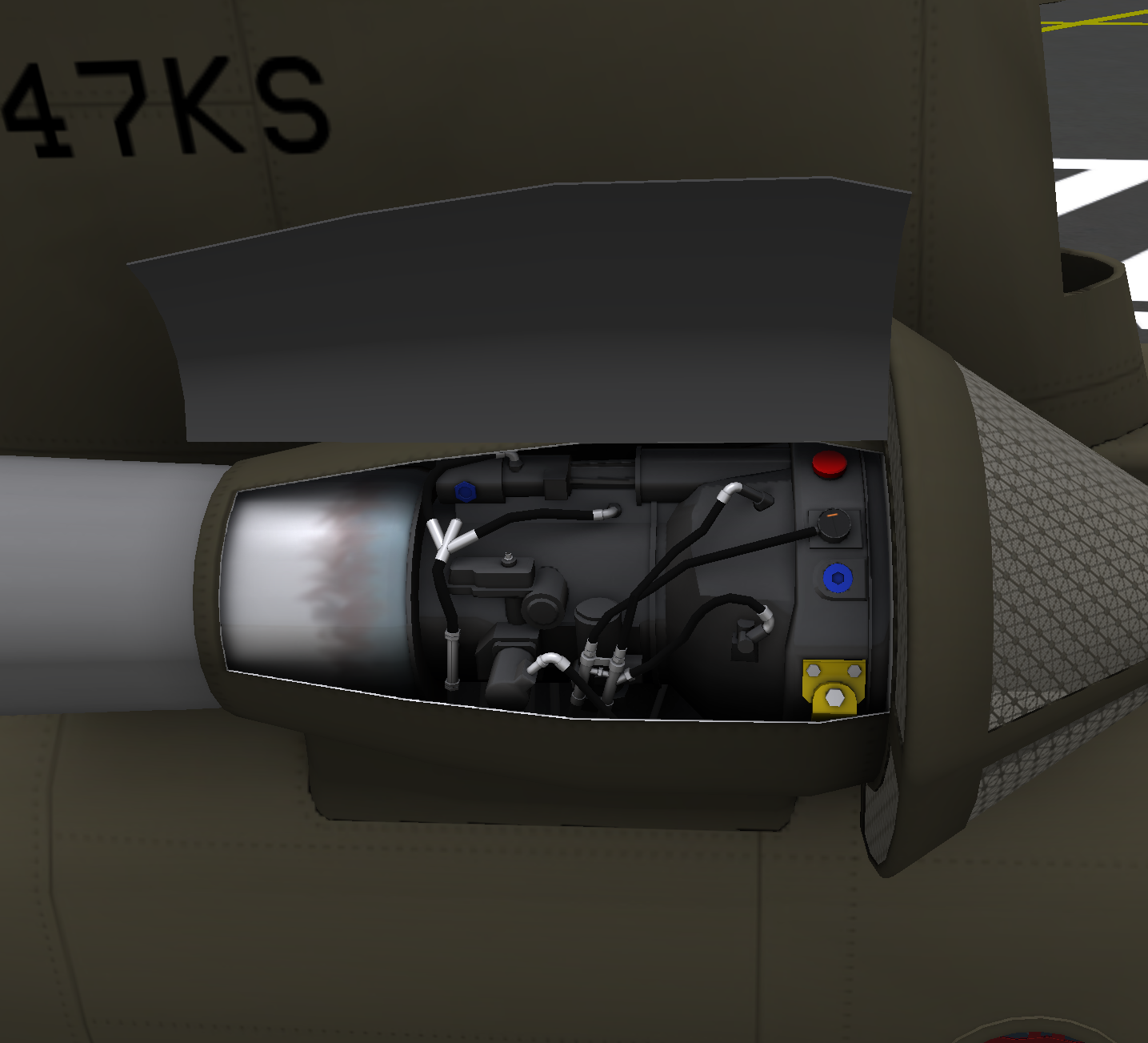
The engines are located on either side of the aft pylon. The engine on left side when looking forward is the #1 engine, and the engine on the right side is the #2 engine. Each engine has a cowling that can be opened for access to the internals. Click on the engine to check for damage, or repair any existing damage.
Each engine has 12 quart oil reservoir. Engines should not be operated with less than 6 quarts. The oil level is detected by a float mechanism. This float mechanism triggers the low oil warning lights in the cockpit, and an orange indicating line near the forward section of the engine. Click on the red cap to add two quarts of oil to an engine.
3 MAINTENANCE PANEL
The maintenance panel is located on the right side of the aircraft in the rear near the ramp. The flight engineer should periodically monitor the panel for indications of transmission or hydraulic issues.
3.1 Transmission
The transmission section of the maintenance panel contains 5 rows of warning lights. Each column shows the status of one of the transmissions systems. The rows are:
- CHIP DETECTOR - Indicates metal fragments have been detected in the affected system. A CHIP light indicates an impending catastrophic failure. The helicopter should land immediately in the event of a CHIP light.
- DEBRIS SCREEN - Indicates the oil debris screen is partially or totally blocked impeding the flow of oil through the transmission.
- MAIN OIL PRESS - Indicates oil pressure in the affected system is low.
- AUX OIL PRESS - Indicates oil pressure in the affected auxiliary system is low.
- OVERTEMP - Indicates the oil temperature in affected system is above limits. Continued operation with an OVERTEMP can lead to damage of that system.
3.2 Engine Chip Lights
Below the transmission section are the engine chip detector lights. These lights indicate that metal fragments have been detected in the engine oil and that an engine failure is possible. The effected engine should be shut down an secured immediately in the event of an engine chip light and the helicopter should be landed as soon as practicable.
3.3 Ground Contact
Two ground contact lights are located next to the engine chip detector lights. These lights indicate the rear wheel compression switches have been activated. These lights should be on while the helicopter is on the ground.
3.4 Hydraulic System
Two rows of gauges show the pressure and temperature of the hydraulic systems. These should be monitored periodically for normal readings.
Below the temperature gauges are the reservoir level gauges. The flight control hydraulic systems share a single gauge with a switch to select which system fluid level to show. The utility hydraulic level gauge has two scales depending on whether the ramp is up or down. When a level gauge is indicating below the ADD line, hydraulic fluid should be added to the appropriate system.
A "LEVEL CHECK" button is located next to the level gauges. This can be used to display hydraulic fluid levels when the aircraft is shut down. Press and hold the button to display the current fluid level.
Additional hydraulic system warning lights are located below the level gauges. FILTER CHANGE lights indicate a hydraulic fluid filter needs to be replaced. PUMP FAULT lights indicate that the pump for a particular systems has hard failed and requires repair.
3.5 System Test
A ground test switch is located in the lower right corner of the panel. When switched to TEST, all panel lights will illuminate.
4 TRANSMISSION SYSTEMS
The Chinook has five transmission gearboxes, each of which must be individually inspected, and each with its own lubrication system. Min and max oil levels for each system are as follows:
| Fluid | Max Capacity (quarts) | Min Capacity (quarts) |
|---|---|---|
| Forward Transmission | 26 | 13 |
| Aft Transmission | 41 | 21 |
| #1 Eng. Transmission | 10 | 5 |
| #2 Eng. Transmission | 10 | 5 |
| Combining Transmission | 20 | 10 |
The following sections will describe the access points of the oil filler caps and inspection points for each transmission.
4.1 Forward Transmission
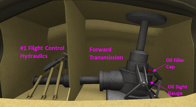
The forward transmission (see Figure 3) is located in the forward pylon. Access is provided through a panel on the right side of the pylon. Click the forward transmission to check for damage or repair it if it is damaged. A sight gauge near the bottom of the transmission indicates the fill level the transmission oil. Click the red filler cap to add two quarts of oil to the system.
4.2 Combining and Engine Transmissions
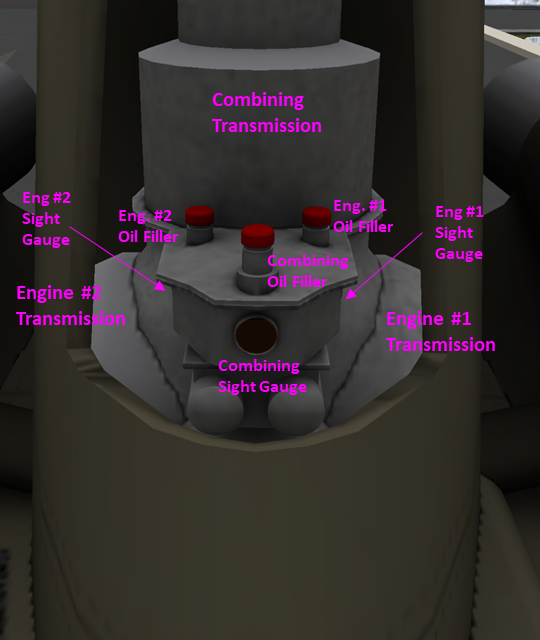
The combining, engine #1 and engine #2 transmissions are accessed through the front of the aft pylon (see Figure 4). Each transmission is independently clickable to inspect or repair. Each transmission also has its own filler cap and sight gauge. The sight gauges for the engine #1 and #2 transmissions are on the sides of the oil reservoir on the front of the combining transmissions.
4.3 Aft Transmission
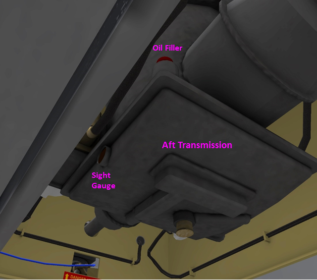
The aft transmission (see Figure 5) is accessed from inside the helicopter over the rear ramp. Click the transmission to check its condition or repair it if necessary. An oil level sight gauge is located on the side of the transmission, and a filler cap is above the oil pan at the bottom of the transmission.
5 HYDRAULIC SYSTEMS
The Chinook has three hydraulic systems with the following min. and max. fluid capacities:
| Fluid | Max Capacity (quarts) | Min Capacity (quarts) |
|---|---|---|
| #1 Flight Control Hydraulics | 9.6 | 8 |
| #2 Flight Control Hydraulics | 9.6 | 8 |
| Utility Hydraulics | 21.6 | 18 |
5.1 Hydraulic Fluid Filling
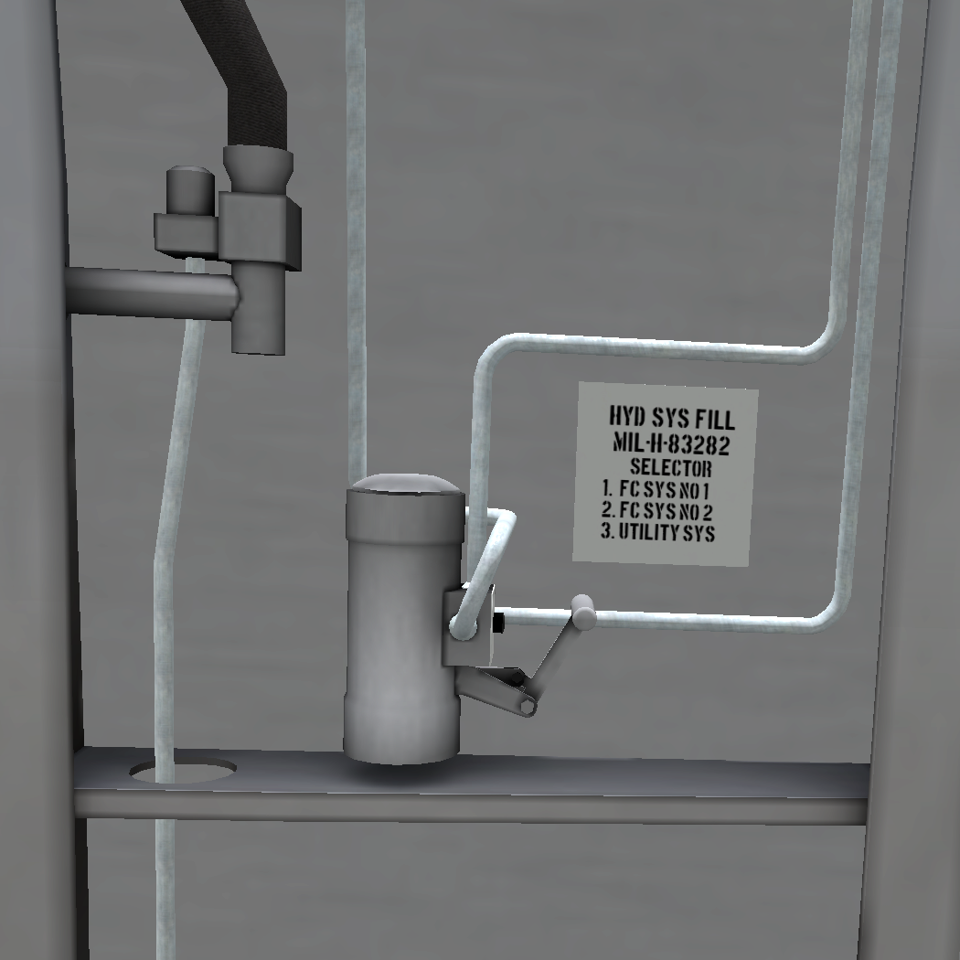
Hydraulic fluid is added through a common fill point in the aft portion of the helicopter near the ramp (see Figure 6). To add fluid use the following procedure:
- Select the desired hydraulic system with the knob on the front of the filler cylinder.
- Open the flap on the top of the filler cylinder.
- Click on a can of hydraulic fluid on the floor below the cylinder to transfer 2 quarts of fluids to the cylinder.
- Click the pump knob once to lower it, and again to pump fluid into the selected system.
- Repeat above steps until hydraulic fluid is at desired level.
5.2 #1 Flight Control Hydraulics
The #1 flight control hydraulic pump is located in the forward pylon behind the forward transmission (see Figure 3). Click on the system to check for faults and repair if necessary.
5.3 #2 Flight Control and Utility Hydraulics
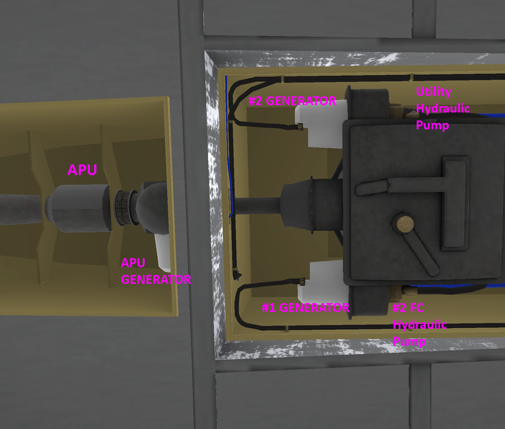
The #2 Flight Control and Utility Hydraulic pumps are located on the accessory section on the bottom of the aft transmission (see Figure 7). Click on a hydraulic pump to check its status, or repair it if it is broken.
6 ELECTRICAL SYSTEMS
The #1 and #2 generators are located on accessory section of the aft transmission (see Figure 7), opposite to the hydraulic pumps. The APU generator is attached to the APU, aft of the transmission. Click on a generator to check its status, or repair it if it is broken.
7 FIRE SUPPRESSION SYSTEMS
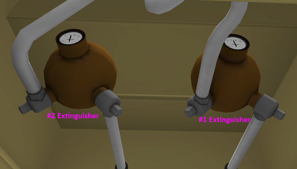
Two engine fire suppression bottles are located forward of the aft transmission (see Figure 8). Each bottle can be used for either engine. A pressure gauge is attached to each bottle to show its charge level. The pilot should ensure both bottles are at or above 500 psi before flight. Click a bottle to recharge it.
8 OTHER SYSTEMS
The APU and the rotor system may also be inspected and repaired when necessary by clicking on them.
