Difference between revisions of "H-160/Systems"
(→LIGHTING) |
(→CAUTION AND ADVISORY DISPLAY) |
||
| Line 309: | Line 309: | ||
===CAUTION AND ADVISORY DISPLAY=== | ===CAUTION AND ADVISORY DISPLAY=== | ||
| − | The CAD (Caution and Advisory Display) is located on the bottom portion of the PFDs on the pilot and copilot side (see ). This boxed area shows various caution and advisory alert messages about the status of the helicopter. Messages are displayed in three columns. The left column shows messages related to the #1 engine, the center column shows general messages and the right column shows messages related to engine #2. | + | [[File:H160-cad.png|thumb|right| |
| + | <figure id="fig:cad"><caption> | ||
| + | CAD (Caution and Advisory Display)</caption></figure>]] | ||
| + | |||
| + | The CAD (Caution and Advisory Display) is located on the bottom portion of the PFDs on the pilot and copilot side (see <xr id="fig:cad"/> ). This boxed area shows various caution and advisory alert messages about the status of the helicopter. Messages are displayed in three columns. The left column shows messages related to the #1 engine, the center column shows general messages and the right column shows messages related to engine #2. | ||
When all engines are operating and the helicopter is ready for flight, all alert messages should be out. However, when electrical power is first applied but the engines are not yet online, it is normal for certain messages to be displayed. Possible alert messages are listed below. | When all engines are operating and the helicopter is ready for flight, all alert messages should be out. However, when electrical power is first applied but the engines are not yet online, it is normal for certain messages to be displayed. Possible alert messages are listed below. | ||
Revision as of 00:30, 23 October 2021
SECTION 2. AIRCAFT AND SYSTEMS DESCRIPTION AND OPERATION
Contents
1 HELICOPTER
1.1 General
The Shergood/VSL H-160 is a twin-turbine engine single-rotor helicopter certified for day/night operations in both visual and instrument conditions. Missions include executive transport, utility transport, cargo, and medical transport. It is powered by two Safran Arrano turobshaft engines producing 1,100 to 1,300 hp each. Each engine drives the main transmission and can be decoupled through independent freewheeling clutches. Each engine also powers an independent primary generator. In addition, an emergency generator is attached to the main rotor drive shaft and thus can produce electrical power as long as the rotors are turning.
1.2 Gross Weight
The maximum gross weight is 12,500 pounds.
1.3 Landing Gear Systems
The landing gear is the retractable tricycle type system with two main gear and one nose gear. The nose gear is castoring, but can be locked by the pilot to prevent unwanted yaw on the ground. Gear is raised and lowered by an electrical motor which can be powered from either the DC1 or DC2 buses.
When retracted, the wheels fold into wheel wells under the aircraft. The wheel wells are the open type without doors.
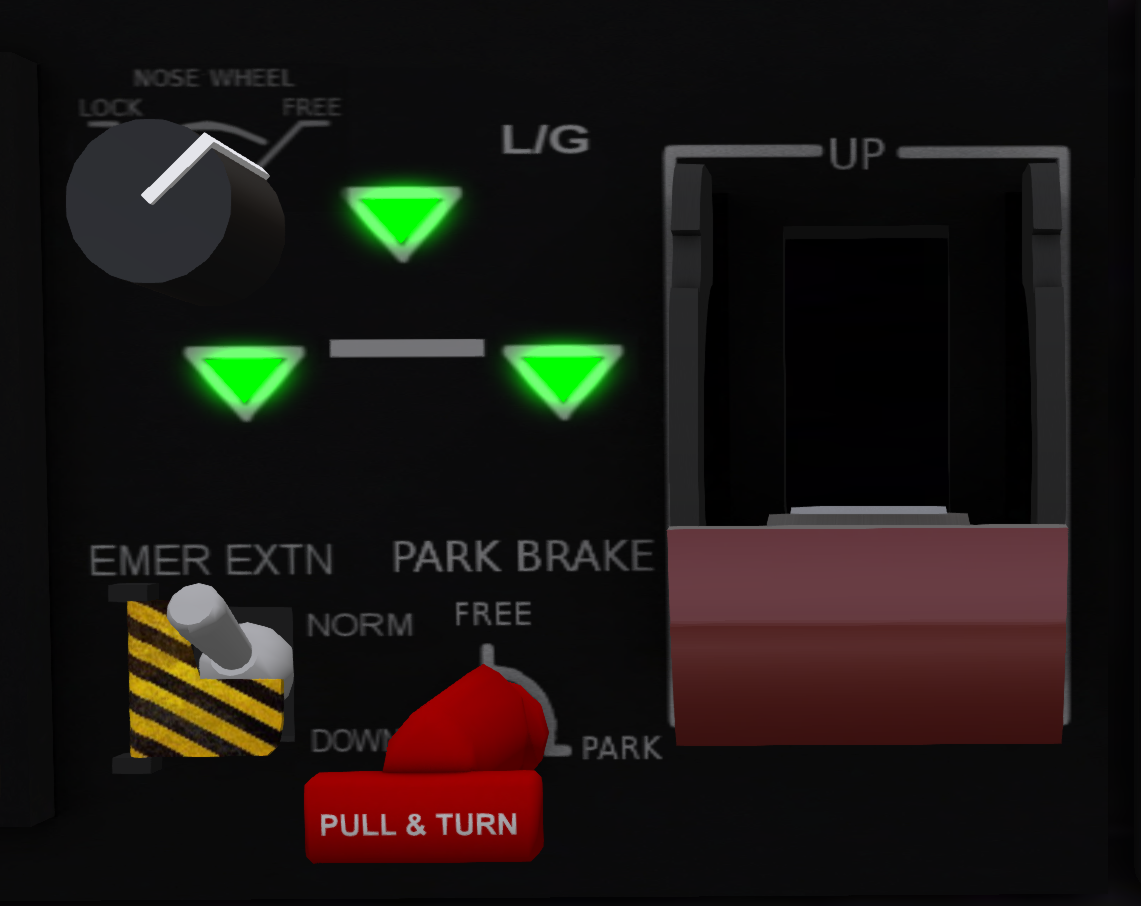
The landing gear is controlled by a sliding lever on the slant panel near the pilot side (see Figure 1). Slide the lever to the up position to retract the gear, and to the down position to deploy the gear. Three indicator lights show the position of each wheel with green for full down, amber for full up and red for in-transit. In the event that the gear handle is in the down position and three green lights do not illuminate, the pilot should investigate the cause before landing.
1.3.1 Emergency Operations
In the event that the gear fail to descend when the gear activation lever is moved to the down position, the emergency extend (EMER EXTN) system may be engaged. To use the emergency extend system:
- Return landing gear lever to the UP position.
- Open the guard and move the emergency extend switch to the DOWN position.
- Move the landing gear lever to the DOWN position.
1.3.2 Nosewheel Lock System
A nosewheel lock switch is located in the upper left corner of the landing gear panel. The switch has two positions LOCK and FREE. When the nosewheel is in the LOCK position, the aircraft will resist turning while on the ground. While in the FREE position, the nosewheel will turn for easier ground operations.
1.3.3 Parking Brake
The parking brake is located in the lower center of the landing gear panel. The parking brake has FREE and PARK positions. The parking brake is activating by pulling and turning the red lever (or clicking in SL).
1.4 Primary Flight Display (PFD)
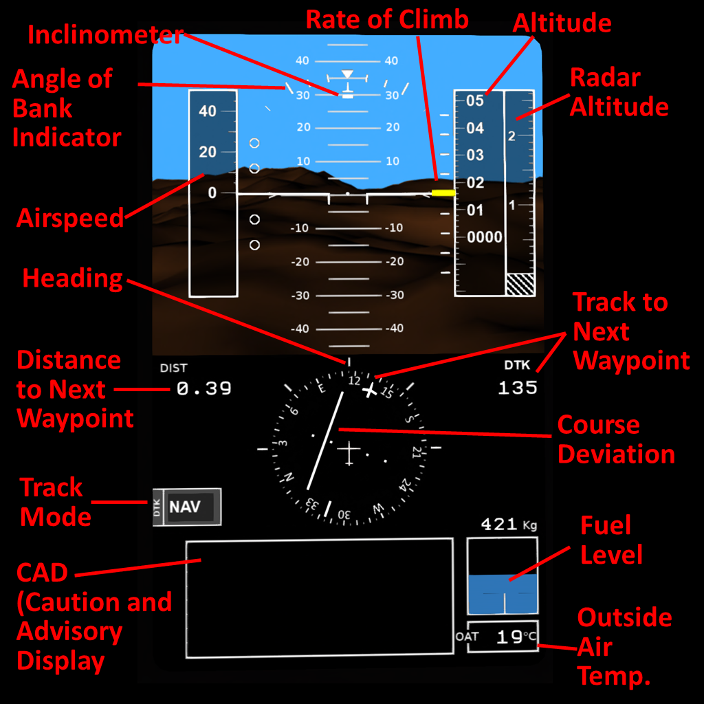
Both pilot and co-pilot are provided a PFD panel on the outmost panel position at each station. This panel provides the primary information used in flight. The upper portion of the display shows the attitude of the aircraft in pitch and bank with the following overlaying information:
- Inclinometer - Small white rectangle that moves left/right under the reference mark to show deviation from coordinate cruise flight. This display serves the same function as the ball-in-tube type inclinometer.
- Angle of Bank Indicator - Shows the current bank angle with marks at 0, 10, 20, 30 and 45 degrees.
- Airspeed - Shows the current airspeed in knots
- Heading - Shows the current heading based on the directional gyro
- Distance to Next Waypoint - If a course has been entered into the FMS, this is the distance in km to the next waypoint.
- Track Mode - The mode for the course indicator shown on the DG. In DG mode, the course is manually entered, in NAV mode the course is heading from the last waypoint to the next waypoint.
- CAD (Caution and Advisory Display) - Shows any caution or advisory messages such as engine CHIP indications, overtemps, etc.
- Rate of Climb - Shows the rate of climb or descent. Each mark on the scale represents 500 feet/min.
- Altitude - Altitude in feet above sea level. Will read 0 when at the SL system water level.
- Radar Altitude - Height in feet above in land or structures below the current position. RA switches on upper panel must be engaged to enable display of radar altitude.
- Track to Next Waypoint - If in NAV mode, this shows the desired heading to the next waypoint. If in DG mode, this shows the manually entered desired heading.
- Course Deviation - Only active in NAV mode. Shows the deviation between current position and the desired track.
- Fuel Level - Shows remaining fuel both graphically and in Kg.
- Outside Air Temp - Shows the temperature in Degrees Celsius outside the aircraft.
1.5 Vehicle and Engine Monitoring Display (VEMD)
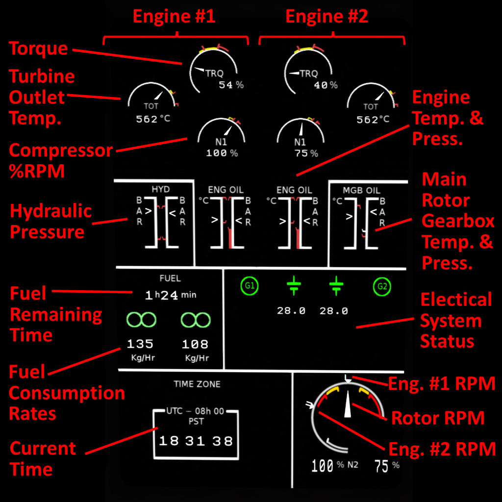
The pilot and copilot are also each provided with a Vehicle and Engine Monitoring Display (VEMD) located next to their respective PFDs. The upper potion of this display shows the torque, TOT and N1 for each engine, respectively.
- Torque - Total torque produced by each engine. Lower red line in is the AEO (All Engines Operating) limit, and the opper red line is the OEI (One Engine Inoperative) limit.
- TOT (Turbine Outlet Temperature) - The temperature of the hot gas at the turbine outlet.
- N1 - Percent RPM of the compressor stage.
- Hyd Press. - Pressures of the #1 and #2 hydraulic systems
- Engine Temp & Press. - Presures and temperatures for each engine.
- Main Rotor Gearbox Temp. & Press. - Temperature and pressure of the main rotor gearbox.
- Fuel Remaining Time - Amount of fuel remaining in hours and minutes based on standard cruise power. The displayed value is scaled down when using higher than standard power.
- Fuel Consumption Rates - Amount of fuel in Kg/Hour used by each engine.
- Electrical System Status - Shows status of batteries, generators and external power.
- Current Time - Current time SLT.
- RPM - The Engine(N2) and rotor RPMs are shown on a common three indicator dial. The N2 for each engine is shown on a small triangle marked with the engine number on the outside of the dial, while the rotor RPM is shown with a needle inside the dial. The lower portion of the dial marked with a white range indication represents RPMs below 50%. The yellow region shows the caution region for normal operation and the red region indicate overspeed and underspeed regions.
2 EMERGENCY EQUIPMENT
2.1 Engine Fire Detection System
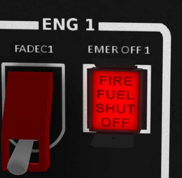
The engine fire detection/extinguisher system is designed to extinguish fires in the engine compartment only. The system is operated by two knobs labeled "FIRE FUEL SHUT OFF" above the engine control switches on the upper panel above the pilot (see )a. A separate fire bottle is available for each engine.
When a fire is detected in an engine, the "FIRE FUEL SHUT OFF" indication will illuminate on the handle for the affected engine, and an alarm will sound. To discharge agent into an engine, simply pull (click) on the handle.
2.2 Cargo Fire Detection System
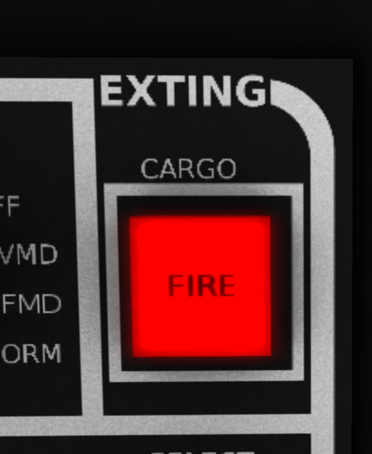
The H160 is also equipped with fire detection and extinguishing systems for the cargo area. When a cargo area fire is detected, the a button on the upper left console (see )b will illuminate and a warning alarm will sounds. Press the button to discharge the fire extinguisher and put out the fire.
2.3 Emergency Floats
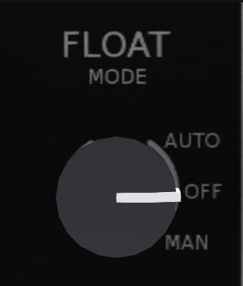
The H-160 is equipped with emergency floats for overwater travel. A knob on the slant panel (see Figure 6) is used to arm the system. The switch has three positions OFF to disable the flotation system, MAN for manual release only, and AUTO to enable both automatic and manual release. When in AUTO mode, a sensor in the rear gear well will detect when the aircraft is submerged an automatically inflate the floats. When the system is armed in either MAN or AUTO mode, an indicator light below the mode switch will light up and show ARM.
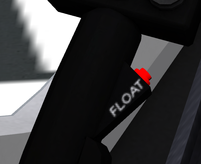
Floats are manually deployed by pressing the button on the collective (see Figure 7) or using the "floats" chat command. As a special feature for SL owners of the H-160, the floats can be repacked by simply turning the mode switch to OFF.
3 ENGINES AND RELATED SYSTEMS
3.1 General
The Shergood/VSL H-160 is equipped with two Safran Arrano turboshaft engines mounted above the main cabin just aft of the main transmission. Each engine is capable of producing up to 1,300 shaft horse power. The engines use a two-stage centrifugal compressor, a reverse-flow combustion chamber and a single-stage power turbine. Each engine is kept lubricated by an 8 quart oil reservoir located at the inlet side of the engine. A sight glass below the fill cap shows the level of oil in the engine. The sight glass will show empty when there are 4 or less quarts of oil in the engine.
3.2 Engine Control Switches and FADEC
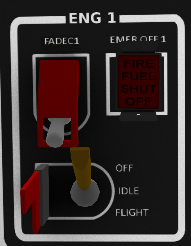
Engine control switches are located on the overhead switch panel (see Figure 8). Each switch has OFF, IDLE and FLIGHT positions. A FADEC (Fully Authority Digital Engine Control) unit for each engine performs the actual control of the engine based on the position of the switch. The FADEC oversees engine start and maintains proper operating RPM during flight and performs a controlled shutdown at the end of flight. The switches for the FADEC are guarded and normally left in the ON position except in the case of a FADEC failure.
Moving an engine control switch from OFF to IDLE causes the FADEC to automatically initiate the sequence of events necessary to start the engine and bring it to 75% RPM. Note that the FADEC must be receiving electrical power in order for the start sequence to initiate. If a FADEC is turned off, or has failed, the affected engine will not start even if the control switch is moved to the IDLE position. From IDLE, an engine is advanced to full RPM by moving the flight control switch to the FLIGHT position.
During cruise flight, the amount of power that must be delivered to the rotors changes as the collective pitch is changed. The FADEC automatically detects these changes and responds be increasing or decreasing engine power to maintain a constant RPM. In the event of a FADEC failure, engine RPM will vary in response to changes in collective pitch resulting in the possibility of a low RPM condition or overspeeding the rotors. In this event, it is recommended that that the pilot shut down the affected FADEC and engine and land as soon as practical using the remaining engine.
Normal engine shutdown is also governed by the FADEC. While it is possible to shut down an engine by moving the engine control switch to OFF even with a failed or disabled FADEC, this is not recommended.
4 FUEL SYSTEM
The fuel supply system on the H160 consists of a single 276 gallon tank with a baffle at the bottom creating two 32 gallon partitions, one for each engine. The baffles ensure that at least 32 gallons are reserved for each engine. The system is entirely gravity fed. No pumps are required to move fuel from the main upper portion of the tank to the lower engine-specific portion.
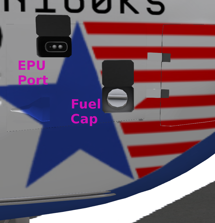
The fuel cap is located on the left side of the aircraft behind the passenger compartment (see Figure 9). Either KellyFuel or DSA fuel systems may be used.
5 FLIGHT CONTROLS AND AFCS
5.1 Flight Controls
The helicopter is controlled by changing the pitch of the main rotor blades collectively or cyclically, using the collective lever or cyclic stick. The collective lever is used to increase total thrust, while the cyclic controls the direction of that thrust to initiate forward, sideward ot backward motion. All controls are hydraulically assisted. When one or more hydraulic systems are failed or disabled, control responsiveness will be reduced.
The pedals are used to compensate for main rotor torque, for directional control in a hover and for cordinating turns in cruise flight. Since the main rotors on the H160 turn clockwise (compared to the counter-clockwise rotation of most US made helicopters), right pedal is needed to compensate for torque as collective is increased.
See Chapter 1 - General for details on the Second-Life control options.
5.2 AFCS
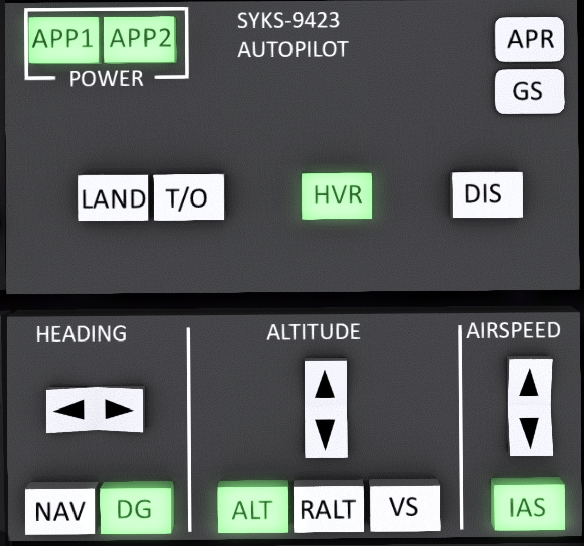
The SYKS-9423 Advanced Flight Control System (AFCS) autopilot can be used to reduce pilot workload by maintaining one or more flight axes of the helicopter. It can be used to maintain airspeed, heading, altitude or any combination of these. The system is comprised of two AFCS computers, sensors, actuators and a common AFCS control panel (see Figure 10 ). The system may be controlled either directly through the panel or through chat commands.
System power is controlled with the APP1 and APP2 buttons in the upper left corner of the AFCS control panel. Each button enabled one of the AFCS computers. While control can be maintained with only one AFCS system active, higher gain control and better responsiveness can be maintained with both systems active.
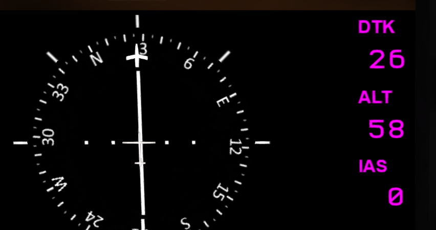
The bottom portion of the control panel shows the basic status of the various AFCS hold functions. Separate sections for heading, altitude and airspeed control are shown. Pressing a button will enable or disable a hold of that parameter. Autopilot status with the specific held values is also shown on the PFD with magenta text (see Figure 11).
Heading hold has two sub-modes, NAV and DG. In NAV mode, the heading is set directly from the FMS/GPS based on the heading to the next waypoint. An intercept to the selected course will be flown if necessary. In DG mode, the AFCS will hold a manually entered heading which can be adjusted through the control over the the buttons or with the "ap hdg n" chat command. The selected heading will be shown on the HSI as both the indicating arrow and a digital display of the current DTK (Desired Track) heading. Note that the heading adjustment buttons can be used even when the AFCS is off or disabled to control DTK heading on the HSI.
Altitude hold has three sub-modes, ALT, RALT and VS. In ALT mode, heading is held based on altitude above SL sea level. In RALR (Radar Altitude), a constant height above the ground (system or prim) is held. In VS mode, a programmed vertical speed is maintained.
Finally airspeed hold has a single mode, IAS. When at or below 40 knots, an airspeed hold will also control lateral cyclic to maintain zero sideways airspeed. Above 40 knots, cyclic is used for directional control.
The following three convenience buttons are also provided on the AFCS panel:
- LAND - Enables all three holds, with heading set to current heading, airspeed set to 0 and target altitude to 0 to initiate a landing.
- T/O - Enables all three holds, with heading set to current heading, airspeed set to 0 and target altitude to 20 feet above the current altitude to initated a takeoff.
- HVR - Enables all three holds, with heading set to current heading, airspeed set to 0 and target altitude set to the current altitude.
Disconnect of the AFCS can be accomplished by pressing the DIS button, using the included spacebar gesture, or using the "ap dis" chat command. The AFCS will automatically disconnect if the rotor RPM falls below 80%, or if exessive turbulance is encounter. A tone will accompany AFCS disconnect.
5.3 AFCS Chat Commands
The following chat commands can be used with the AFCS:
| Command | Description |
|---|---|
| ap IAS | Toggle airspeed hold |
| ap ALT | Toggle altitude hold |
| ap RALT | Toggle radar altitude hold |
| ap VS | Toggle vertical speed hold |
| ap HDG | Toggle heading hold |
| ap DIS | Disconnect autopilot |
| ap IAS n | Set the target airspeed to n |
| ap HDG n | Set the target heading to n |
| ap L n | Set the target heading left by n degrees |
| ap R n | Set the target heading right by n degrees |
| ap ALT n | Set the target altitude to n feet |
| ap RALT n | Set the target altitude to n feet above ground |
| ap VS n | Set the target vertical speed n feet per second |
| ap D n | Set target altitude up n feet |
| ap U n | Set target altitude down n feet |
| ap HVR | Enter autohover mode |
| ap TO | Takeoff and enter hover |
| ap LAND | Land at current location |
6 HYDRAULIC SYSTEM
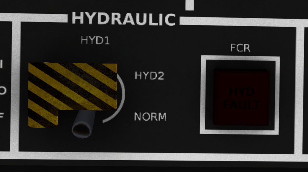
The H-160 has two flight control hydraulic systems. Hydraulic System #1 is powered by the #1 engine, while Hydraulic System #2 is powered by the #2 engine. Additionally Hydraulic System #1 is also powered by an electric pump when the electrical systems is energized. The hydraulics control panel (see Figure 12>) is located on the upper panel above the co-pilot station. A guarded three position switch allows you to select either system individually, or use both systems (NORM). Normally this switch should be left in the NORM position. An indicator light labeled FCR (Flight Controls Ready) is next to the hydraulic switch. This indicator will illuminate red any time one or more of the hydraulic systems is inactive.
In the event of a single system hydraulic failure, it is recommended that a landing be performed as soon as practical so the appropriate repairs can be made. A double hydraulic failure is considered a serious emergency with control of the helicopter being severely limited.
When operating on external power for extended periods of time, the #1 Hydraulic system should be disabled by selecting HYD2 on the Hydraulics Switch in order to prevent constant running of the Electric Hydraulic Pump. Allowing the electric hydraulic pump to run for extended periods of time may cause depletion of hydraulic fluid and damage to the system. The Hydraulic switch should be returned to the NORM position before flight.
7 TRANSMISSION AND ROTORS
Engine power is supplied to the rotors through a mechanical transmission system. The system consists of a forward main transmission and a tail rotor gearbox. Each system has its own lubrication reservoir.
The main transmission includes a mixing unit to combine power supplied by each engine. Normally the power input is balanced so each engine supplies the same amount of torque, but in the event of an engine failure, the operating engine can drive the rotor system independently.
8 ELECTRICAL SYSTEM
8.1 Overview
The H-160 electrical system (see Figure 13) consists of two DC buses #1 and #2. The DC buses normally operate at 28 volts powered through through separate generators driven by the respective engine. Each bus can also be energized by separate 24-volt nickel-cadmium batteries. Most devices in the helicopter are redundantly powered by either DC system.
In the event of a primary generator failure, an emergency generator driven by the main rotor can be enabled. The emergency generator powers both DC buses through diode protectors.
8.2 Electrical Panel
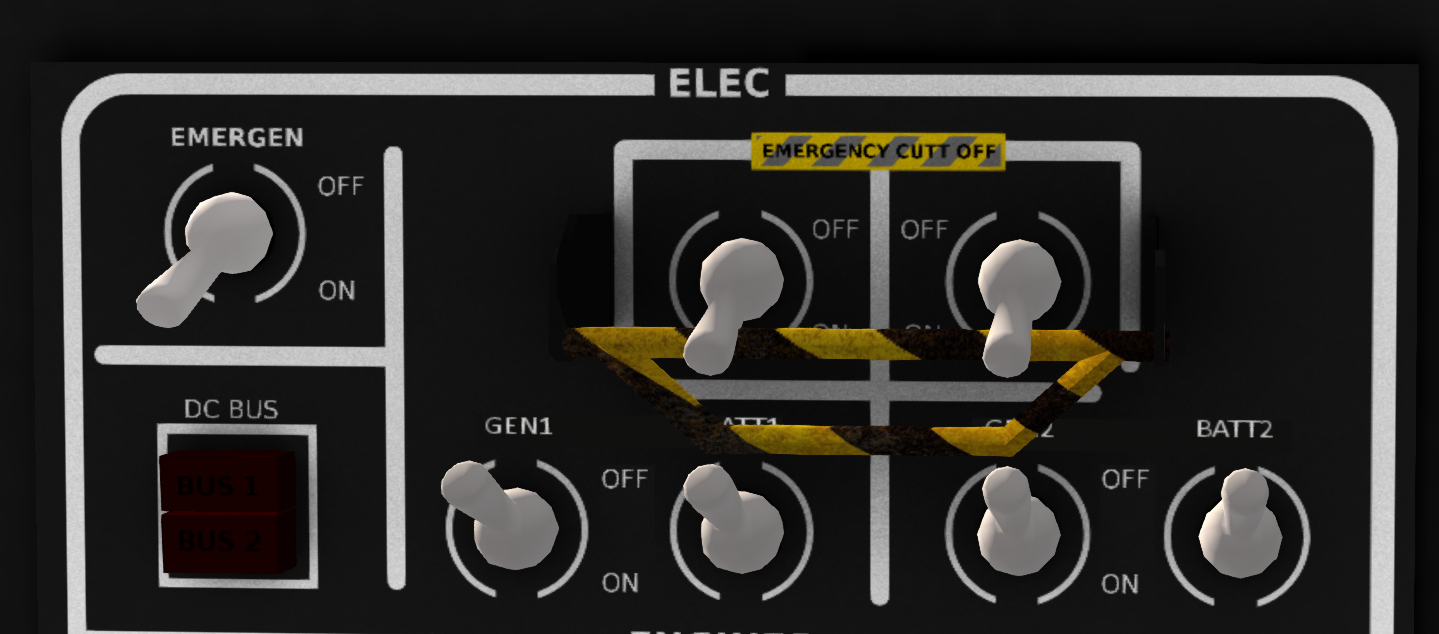
The electrical control panel (see Figure 14) is located on the overhead panel above the pilot station. Switches for the generators and batteries are located along the bottom portion of the panel. Two switches control the generator and battery for the DC1 bus, while two control the generator and battery for the DC2 bus. A DC BUS warning light to the left of the main switches indicates if a BUS is not energized (as long as at least one bus is energized).
The emergency generator switch (labeled EMERGEN) is located in the upper left corner of the electrical panel.
On the top of the panel are two emergency cutoff switches for each bus. A quick-trip bar below them allows both switches to be turned off together quickly in the event of an electrical fire. The cutoff switches will remove all power from a bus.
8.3 Electrical Status
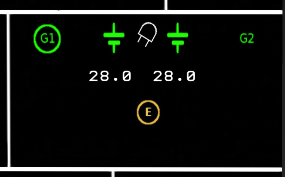
The status of the electrical system is displayed on the VEMD panels on the pilot and copilot sides (see ). The left side of the screen shows the status for the DC #1 Bus while the right side shows the status for the DC #2 Bus.
The following symbols are used on the electrical status screen to indicate the status over the various components of the electrical system:
Below the battery symbols, the voltage level of each bus is shown. When a generator is on or external power is connected, this is typically 28V. When on battery power, 24V will be displayed. In general, external power should be connected for start when the battery level falls below 23V.
9 UTILITY SYSTEMS
9.1 Ice Sensor
The ice sensing system (RP only) is located on the upper panel above the co-pilot station. The ice system detects ice build-up on the rotors and airframe and alters the pilot to dangerous icing conditions.
9.2 Windshield Wipers
The windshield wiper and washer control are located on the slant panel below the main flight display panels. While the controls can be moved, they are currently for RP purpose only. In the event LL implements actual weather, functional wipers may be added to this aircraft.
9.3 Mission Mode
The mission mode switch is located on the upper panel over the co-pilot station. It is intended to configure the aircraft for specific modes such as sling load use. It is only has an effect when certain optional mission equipment is installed.
10 LIGHTING
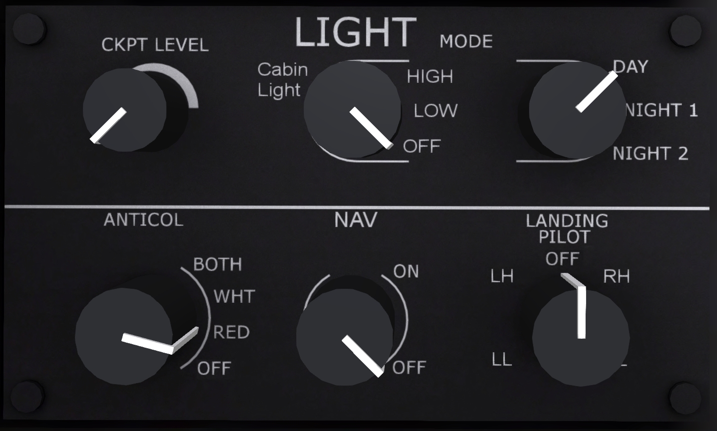
The lighting panel (see Figure 15) is located at the aft-most position on the pilot side of the center console. The upper three knobs control the interior lighting, while the lower three knobs control exterior lighting.
10.1 Interior Lighting
The interior lights are:
- CKPT LEVEL - White, overhead cockpit flood lights with varying intensity levels.
- Cabin Light - Light level in the main cabin with OFF, LOW and HIGH settings.
- (cockpit) MODE - Instrument lighting select with DAY, NIGHT1 and NIGHT2 settings.
10.2 Exterior Lighting
The exterior lights are:
- ANTICOL - The anti-collision light is mounted on the top of the vertical stabilizer. Settings on the switch are OFF, RED, WHT, and BOTH. When enabled, the anti-collision light will flash the selected color. When in the BOTH position it will alternate colors.
- NAV - The red and green navigation/position lights are mounted on the sides of the horizontal stabilizer. The white navigation/position is mounted on the aft side of the vertical stabilizer. These lights should be used for night flight.
- LANDING - The landing light has positions LH (left-high), LL (left-low), RH (right-high) and RL (right-low). Select between the "left" and "right" positions based on the landing pilot. This will cause the beam to be aimed slightly left or right of center. The "high" or "low" settings controls the beam setting. In "high" the beam is aimed further out in front of the helicopter. Use "high" for landing, while "low" can be more useful for ground operations.
11 CAUTION AND ADVISORY DISPLAY
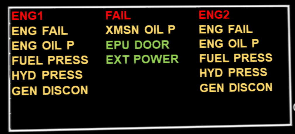
The CAD (Caution and Advisory Display) is located on the bottom portion of the PFDs on the pilot and copilot side (see Figure 16 ). This boxed area shows various caution and advisory alert messages about the status of the helicopter. Messages are displayed in three columns. The left column shows messages related to the #1 engine, the center column shows general messages and the right column shows messages related to engine #2.
When all engines are operating and the helicopter is ready for flight, all alert messages should be out. However, when electrical power is first applied but the engines are not yet online, it is normal for certain messages to be displayed. Possible alert messages are listed below.
11.1 Engine Alerts
| Light | Description |
|---|---|
| ENG FAIL | Engine is failed or not running. |
| ENG OIL P | Engine oil pressure is low |
| ENG CHIP | Engine chip detected |
| FADEC FAIL | FADIC has failed or is not running |
| FUEL PRESS | Fuel pressure is low |
| ENG IDLE | Engine is at idle speed |
| TRAINING | Training mode is enabled |
| TRAIN IDLE | Engine is at simulated idle |
| AUTOPILOT | Autopilot is not running |
| LOW FUEL | Fuel quantity is low |
| HYD PRESS | Hydraulic pressure is low |
| OVSP | Engine is overspeeding |
| GEN DISCON | Generator is off or disconnected |
| STARTER | Engine starter is running |
11.2 Miscellaneous Alerts
| Light | Description |
|---|---|
| LOW RPM | Rotor RPM is less than 90% |
| XMSN CHIP | Chip detected in main transmission |
| TRGB CHIP | Chip detected in tail rotor system |
| XMSN OIL T | Main transmission oil temperature too high |
| XMSN OIL P | Main transmission oil pressure too low |
| ROTOR BRAKE | Rotor brake engaged |
| DOORS | Open door or panel detected |
| EPU DOOR | EPU Door is open |
| EXT POWER | External power is connected |
12 Health and Usage Monitoring System (HUMS)
This helicopter is equipped with a Health and Usage Monitoring System (HUMS). The system is comprised of a set of sensors, a computer and a display system. The sensors monitor various normal and abnormal events in the helicopter, then log and tabulate these events. The HUMS data is displayed by using the MFD3 switch on the overhead panel to select either the FMS (Flight Monitor Display) or the VMD (Vehicle Monitor Display). The data for either output is displayed on the center panel in place of the moving map. The display uses prim media, so you may need to enable media and click on the screen to view it. It may also take 5-15 seconds for the screen to switch modes when changing the setting of the MFD3 switch.
12.1 FMD (Flight Monitor Display)
The FMD display (see Fig. 2-15) shows a log of critical events detected by the HUMS sensors. Select FMD on the overhead FMD3 knob to display it. Each event in the log includes a timestamp, event code, and a short message. In addition to events generated by the sensors, it is possible for the pilot to inject a "marker" event by pressing the "EVENT MAKER" button (see Fig. 2-16) on the upper panel.
The possible event codes are:
| Code | Description |
|---|---|
| START | Engine Startup |
| STOP | Engine Shutdown |
| MARK | Mark button pressed |
| CHIP | Engine chip detected |
| MRCHIP | Main rotor transmission chip detected |
| TRCHIP | Tail rotor gearbox chip detected |
| MRSPEED | Main rotor overspeed detected |
| MRTEMP | Main rotor overtemp detected |
| OVTEMP | Engine overtemp detected |
| STRUCT | Structural overstress or damage detected |
| TORQUE | Torque limit exceeded |
12.2 VMD (Vehicle Monitoring Display)
The VMD display (see ) shows summary information on the vehicle health, and any adverse events that have occurred. Select VMD on the overhead FMD3 knob to display it. For each event type, a count of the number of occurrences is shown. Marker and Start events are considered normal, while other event types are generally abnormal and may require a maintenance action to correct.
