Difference between revisions of "H-34 Choctaw/Systems"
(→Secondary Engine Instruments) |
(→Secondary Engine Instruments) |
||
| Line 151: | Line 151: | ||
|- style="vertical-align:top;" | |- style="vertical-align:top;" | ||
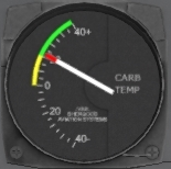
|[[File:S58-carb-temp.png|100px]] | |[[File:S58-carb-temp.png|100px]] | ||
| − | |'''Carburetor Temp.''' - | + | |'''Carburetor Temp.''' - Displays the temperature on the inlet to the carburetor. The carburetor temperature is monitored to help the pilot avoid carburetor icing. |
|-style="vertical-align:top;" | |-style="vertical-align:top;" | ||
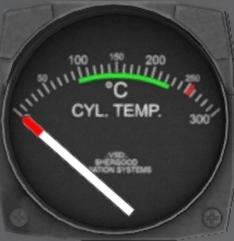
|[[File:S58-cyl-temp.png|100px]] | |[[File:S58-cyl-temp.png|100px]] | ||
| − | |'''Cylinder Temp.''' - | + | |'''Cylinder Temp.''' - Cylinder temperature. The cylinder temperature gauge shows the temperature at the core of the engine. Excessive temperatures can indicate an issue with the engine. This gauge can also be used in start-up and shutdown to ensure adequate time for warm-up and cool-down. |
|-style="vertical-align:top;" | |-style="vertical-align:top;" | ||
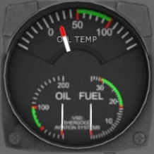
|[[File:S58-oil-tp.png|100px]] | |[[File:S58-oil-tp.png|100px]] | ||
| − | |'''Oil Temp./Press. & Fuel Press.''' - | + | |'''Oil Temp./Press. & Fuel Press.''' - This combined gauge shows the engine oil temperature and pressure as well as the fuel pressure. |
|} | |} | ||
Revision as of 17:40, 28 June 2021
Contents
1 Helicopter
1.1 General
The Shergood H-34/S-58 is a piston engine helicopter designed for transportation of cargo and for search-and-rescue operations in day, night, visual and instrument conditions. The helicopter is powered by a 1,525 hp Wright R-1820-84 Cyclone rotary engine mounted in the nose of the aircraft. A drive shaft from the engine feeds diagonally up to the main transmission mounted under the main rotors. Fuel is carried by three cells on the belly of the aircraft. An entrance door is located on the forward right side of the main cabin with a hydraulic winch mounted over the door.
1.2 Gross Weight
The maximum gross weight is 13,300 pounds.
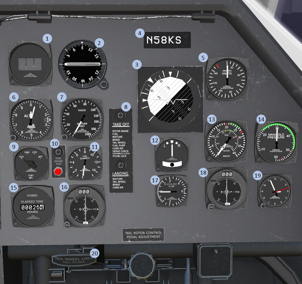
1.3 Pilot-Side Instrument Panel
| 1. DME | 2. RMI | 3. Attitude Indicator | 4. Tail-Number plate |
| 5. Airspeed Indicator | 6. Altimeter | 7. Radio Altimeter | 8. Checklist |
| 9. Fuel Indicator Selector | 10. Fuel Indicator Test | 11. Fuel Indicator | 12. Turn/Slip Indicator |
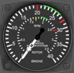
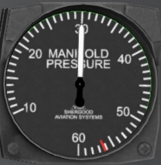
| 13. RPM Indicator | 14. Manifold Pressure | 15. HOBBS Time | 16. #2 VOR |
| 17. VSI | 18. #1 VOR | 19. 8-Day Clock | 20. Tail Wheel Lock |
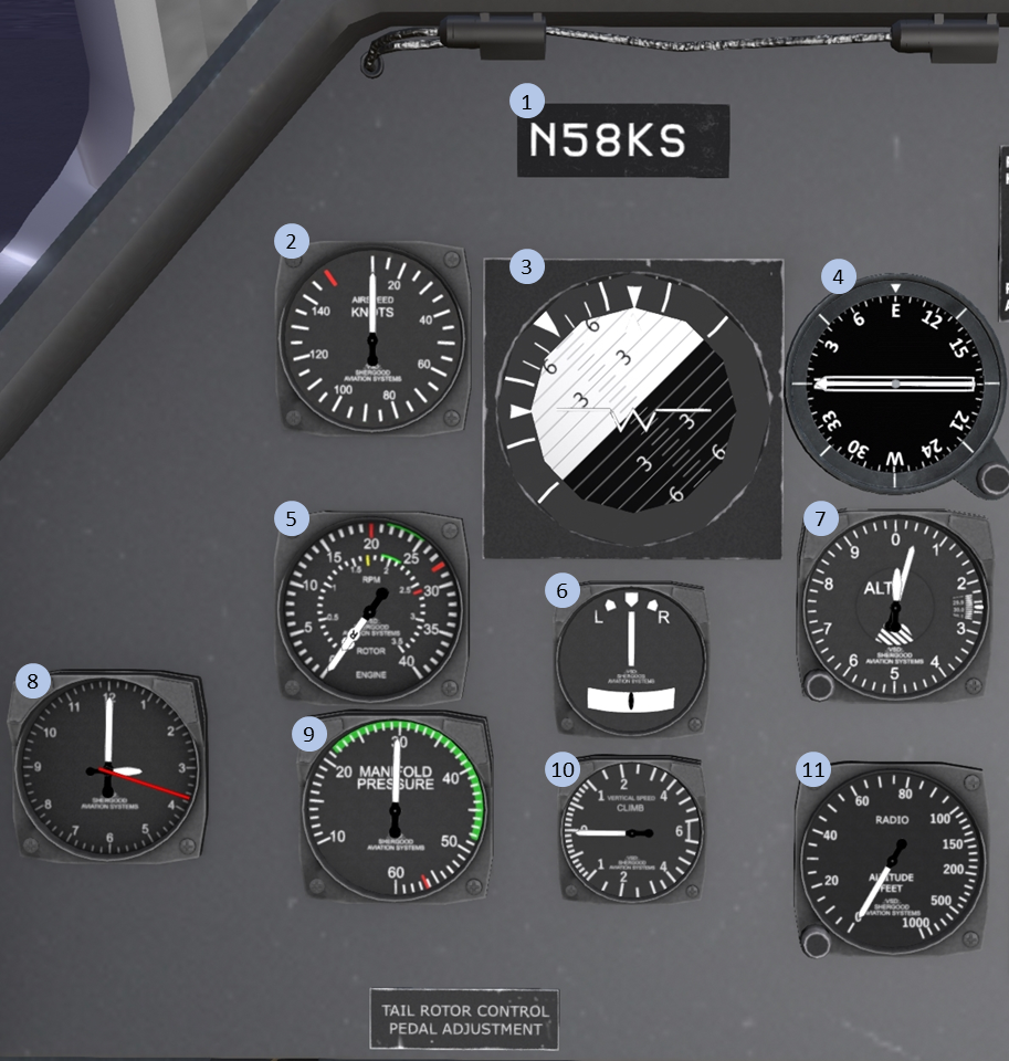
1.4 Copilot-Side Instrument Panel
| 1. Tail-Number plate | 2. Airspeed Indicator | 3. Attitude Indicator | 4. RMI |
| 5. Airspeed Indicator | 6. Turn/Slip Indicator | 7. Altimeter | 8. 8-Day Clock |
| 9.Manifold Pressure | 10. VSI | 11. Radio Altimeter |
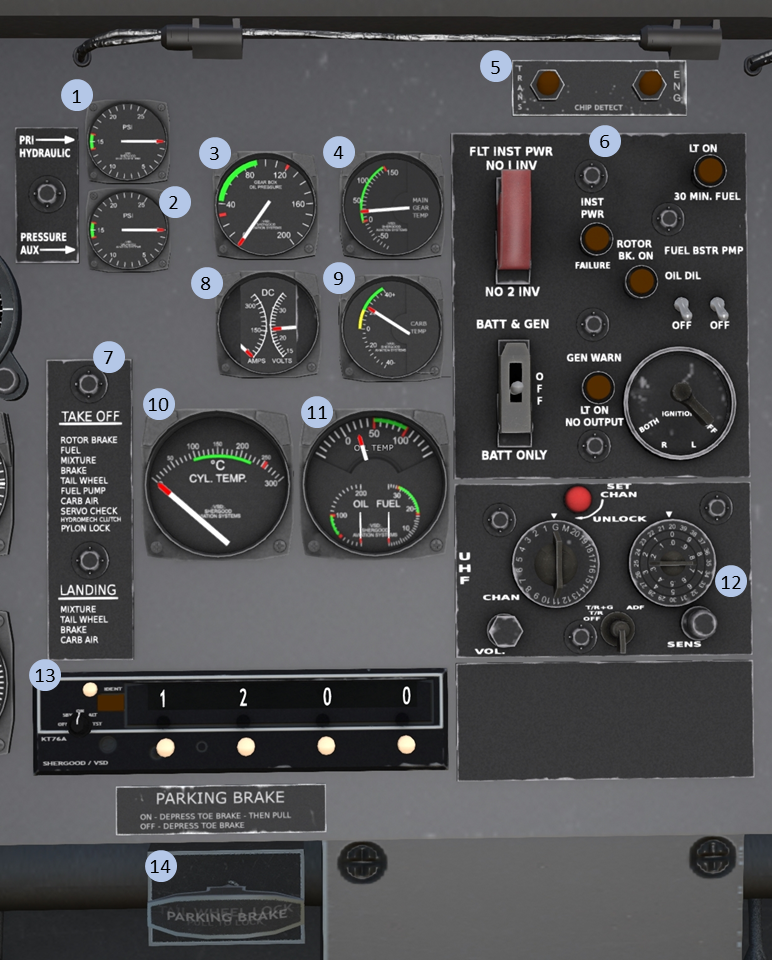
1.5 Center Instrument Panel
| 1. Pri. Hyd. Press | 2. Aux. Hyd. Press | 3. Main Trans. Oil Press | 4. Main Trans. Oil PrTr,ss |
| 5. Chip Indicator | 6. Main Switch Panel | 7. Checklist | 8. DC Volts/Amps |
| 9. Carburetor Temp. | 10. Cylinder Temp. | 11. Oil Temp/Press, Fuel Press | 12. UFH Radio |
| 13. Transponder | 14. Parking Brake |
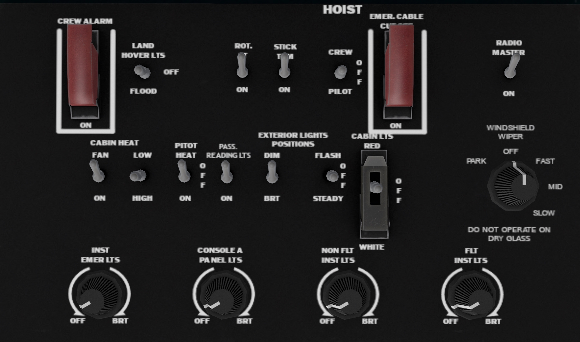
1.6 Overhead Panel
The overhead panel includes various miscellaneous switches including most of the lighting controls, and controls for the hoist and heating systems.
2 Landing Gear System
The S-58 has a fixed landing gear system with two main wheels in the front and a tail wheel in the rear.
2.1 Parking Brake
A parking break is located in front of the co-pilot seat under the center console (Item #14 in Figure 3). Activating the parking brake will increase resistance to ground movement. Click the handle to toggle its position, or use the chat command:
s brake
to toggle it.
2.2 Tailwheel Lock
A tailwheel lock is located on the pilot side below the pilot console. Click the handle to toggle its position, or use the chat command:
s taillock
to toggle it. The tailwheel lock should be used during rotor engagement to prevent the helicopter from turning on the ground during the high-torque stages of engagement.
3 Engines and Related Systems
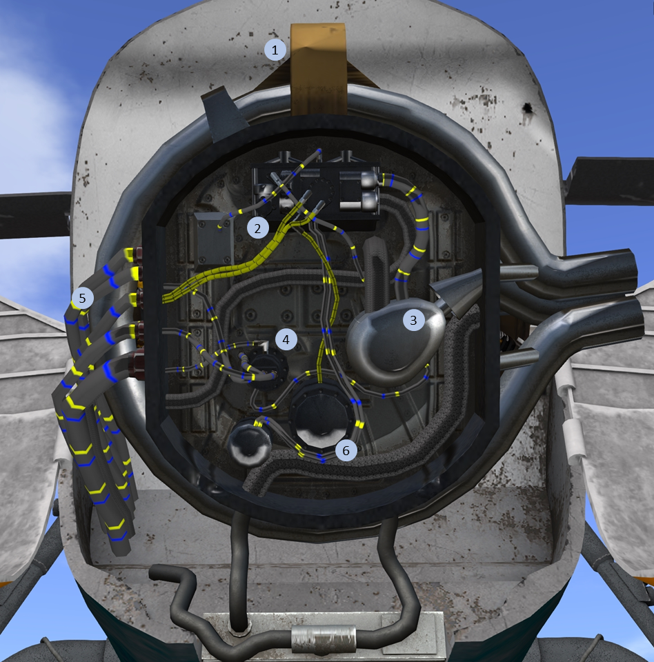
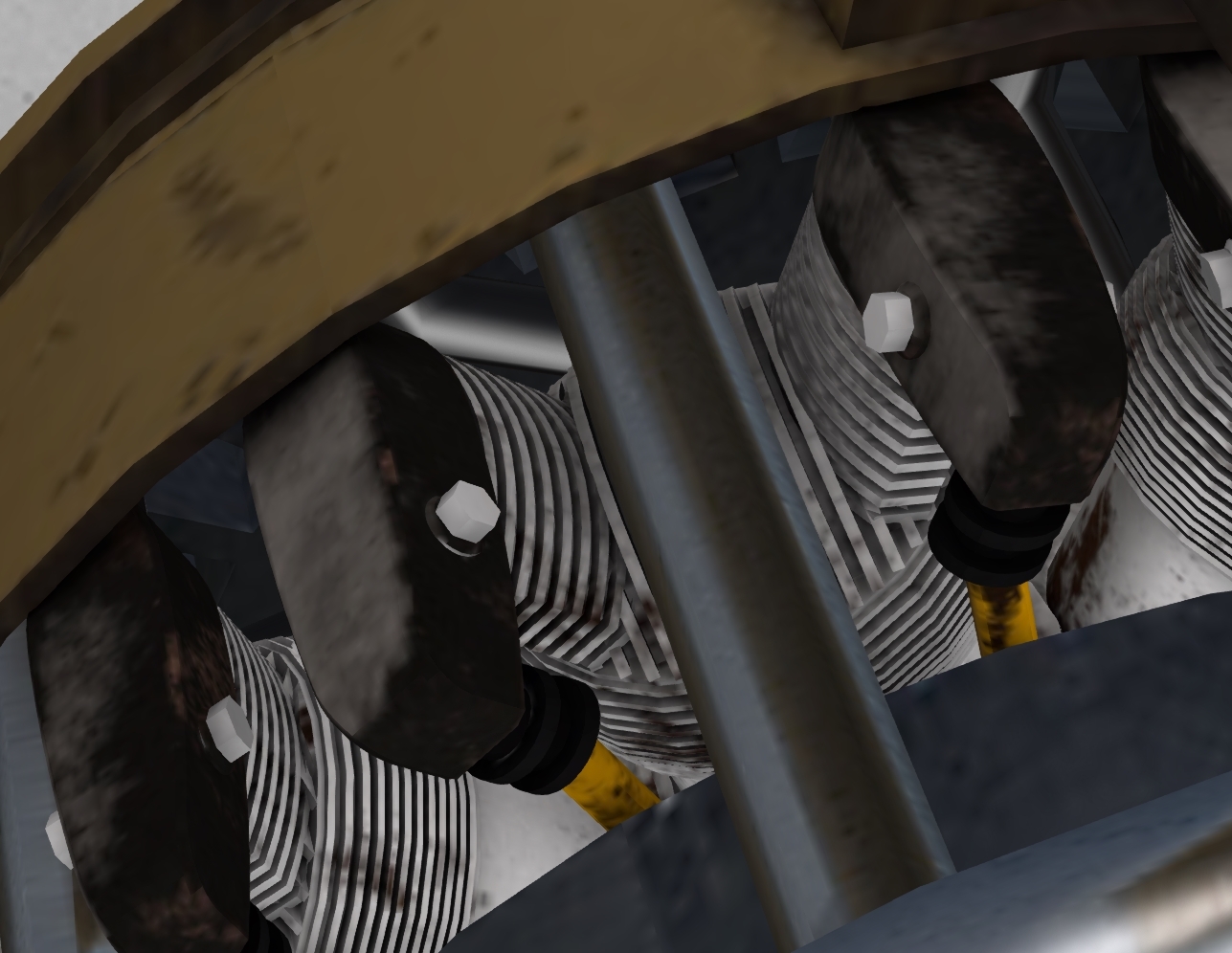
The S-58 is powered by a 1,525 hp Wright R-1820-84 Cyclone, a 9-cylinder rotary engine mounted in the nose of the aircraft (see Figure 5). A drive shaft oriented at 45 degrees passes through he main cabin up to the main transmission. The cylinders (see Figure 6) are arranged around the drive shaft of the engines at 40 degree intervals. Each cylinder two spark plugs, each powered by a different engine driven magneto.
The engine compartment is accessed by two large doors at the nose of the aircraft. Engine accessories including the carburetor, dual magnetos, starter, and auxiliary hydraulic pump are mounted on the front of the engine.
3.1 Throttle
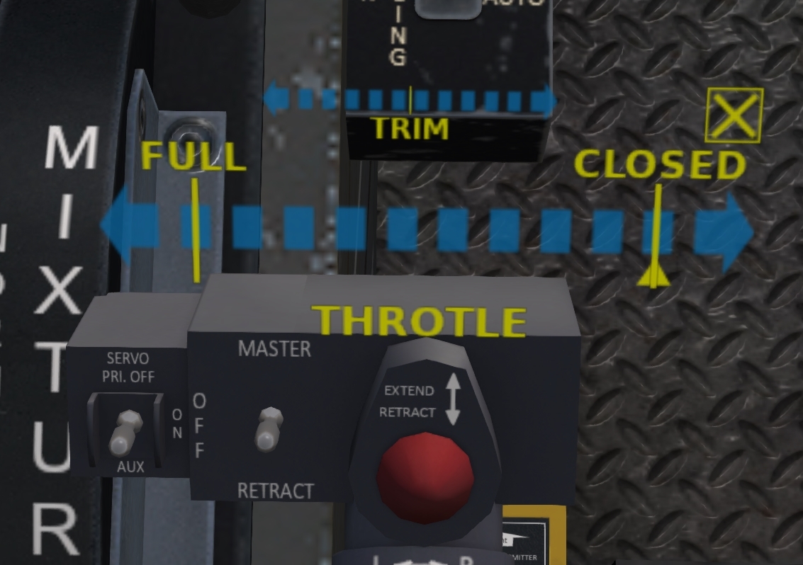
The throttle is controlled by a twist grip on the end of the collective. Clicking on the grip area of the collective will bring up a transparent overlay through which you can control the throttle (see Figure 7). The overlay has a large scale marked FULL and one end and CLOSED at the other. Clicking on this scale will move the throttle to that position. A small yellow triangle under the scale shows the current throttle position.
A smaller scale marked "TRIM" above the throttle scale can be used to make small throttle adjustments. Clicking left of the centerline will increase the throttle by an amount proportional to the distance from the centerline, while clicking to the right of the centerline will decrease the throttle by a proportional amount.
The gesture pack included with the aircraft also includes the following three gestures for controlling the throttle:
| Gesture | Description |
|---|---|
| r | Increase throttle |
| v | Decrease throttle |
| 0 | Close throttle |
