Difference between revisions of "S-61R Pelican/Systems"
(→Primary Engine Instruments) |
(→Primary Engine Instruments) |
||
| Line 280: | Line 280: | ||
==== Primary Engine Instruments ==== | ==== Primary Engine Instruments ==== | ||
| − | {| class=wikitable | + | {| class=wikitable |
! Gauge | ! Gauge | ||
! Description | ! Description | ||
| − | |- | + | |- style="vertical-align:top;" |
|[[File:S61-rpm.png|100px]] | |[[File:S61-rpm.png|100px]] | ||
|N2 | |N2 | ||
| − | |- | + | |-style="vertical-align:top;" |
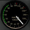
|[[File:S61-torque.png|100px]] | |[[File:S61-torque.png|100px]] | ||
|Torque | |Torque | ||
Revision as of 17:58, 15 June 2020
SECTION 2. SYSTEMS
Contents
- 1 Helicopter
- 2 Emergency Equipment
- 3 APU
- 4 Engines and Related Systems
- 5 Fuel System
- 6 Flight Controls and AFCS
- 7 Hydraulic Systems
- 8 Power Train System
- 9 Rotor System
- 10 Electrical System
- 11 Utility Systems
- 12 Lighting
- 13 Master Alert/Caution Panel
1 Helicopter
1.1 General
The Shergood S-61R is a twin-turbine engine helicopter designed for transportation of cargo and for search-and-rescue operations in day, night, visual and instrument conditions. The helicopter is powered by two 1,400 shp General Electric T58-GE-10 turbo-shaft engines mounted above the main cabin in front of the main transmission. Drive shafts from each engine is connected to the main transmission through a mixing unit such that the rotors will continue to spin even if one engine fails. When the rotors are not turning, an APU (Auxilary Power Unit) can be used to supply electrical power and hydraulic pressure. Fuel is carried in compartments in the lower hull of the helicopter with forward and aft auxilary and main tanks. An entrance door is located on the forward right side of the main cabin, while a hydraulically powered ramp is in the back. The helicopter is fully amphibious with a "flying boat" style design.
1.2 Gross Weight
The maximum gross weight is 22,050 pounds.
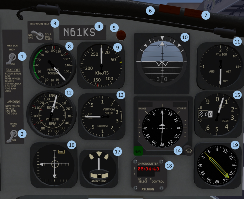
1.3 Pilot-Side Instrument Panel
| 1. Marker Beacon Intensity | 2. RAWS Warning | 3. Fire Warning Test | 4. Tail-Number plate |
| 5. Marker Beacon Light | 6. Fire Warning Light | 7. Master Warning Light | 8. Torque Indicator |
| 9. Airspeed Indicator | 10. Attitude Indicator | 11. Radar Altimeter | 12. Tri-Needle RPM |
| 13. Vertical Speed Indicator | 14. HSI | 15. Altimeter | 16. AFCS Indicator |
| 17. Turn/Slip Indicator | 18. Clock | 19. Radio-Magnetic Indicator |
The right portion of the main panel (shown in Figure 1) is intended primarily for use by the pilot sitting in the right-hand seat.
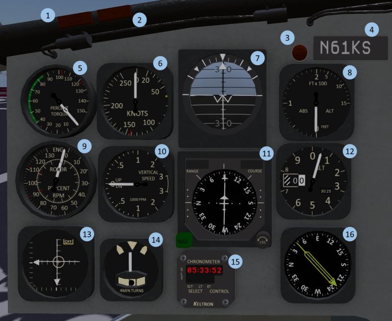
1.4 Co-Pilot-Side Instrument Panel
| 1. Master Caution Light | 2. Fire Warning Light | 3. Marker Beacon Light | 4. Tail-Number plate |
| 5. Torque Indicator | 6. Airspeed Indicator | 7. Attitude Indicator | 8. Radar Altimeter |
| 9. Tri-Needle RPM | 10. Vertical Speed Indicator | 11. HSI | 12. Altimeter |
| 13. AFCS Indicator | 14. Turn/Slip Indicator | 15. Clock | 16. Radio-Magnetic Indicator |
The co-pilot side instrument panel is shown in Figure 2.
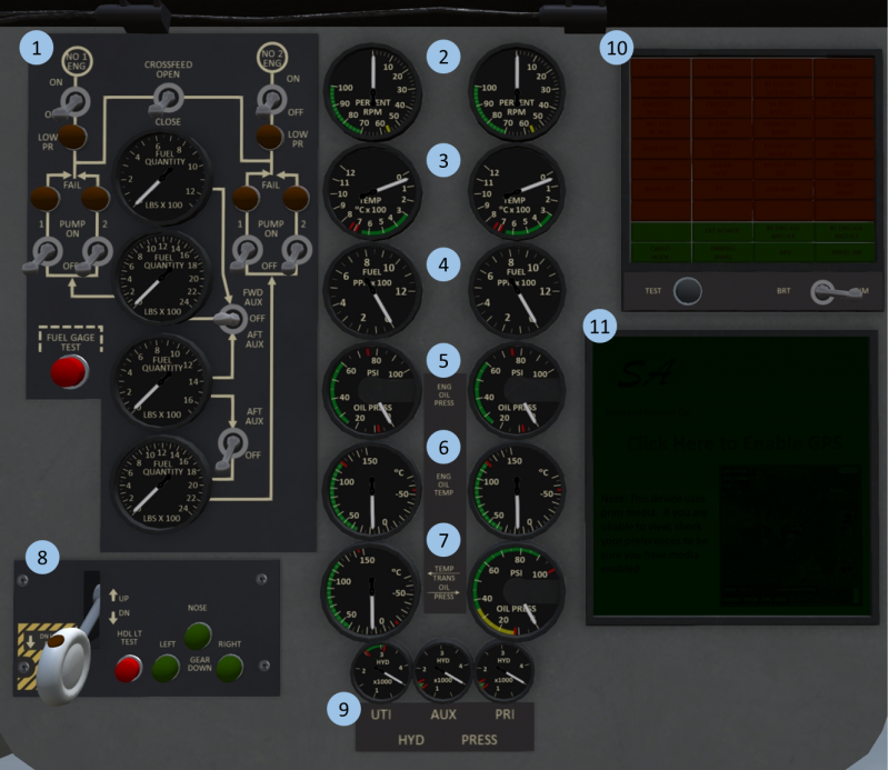
1.5 Center Instrument Panel
| 1. Fuel Panel | 2. N1 Gauge | 3. Turbine Inlet Temp (TIT) | 4. Fuel Flow |
| 5. Oil Pressure | 6. Oil Temp. | 7. Trans. Temp & Press. | 8. Gear Panel |
| 9. Hydraulic Pressure | 10. Warning/Alert Panel | 11. GPS Moving Map |
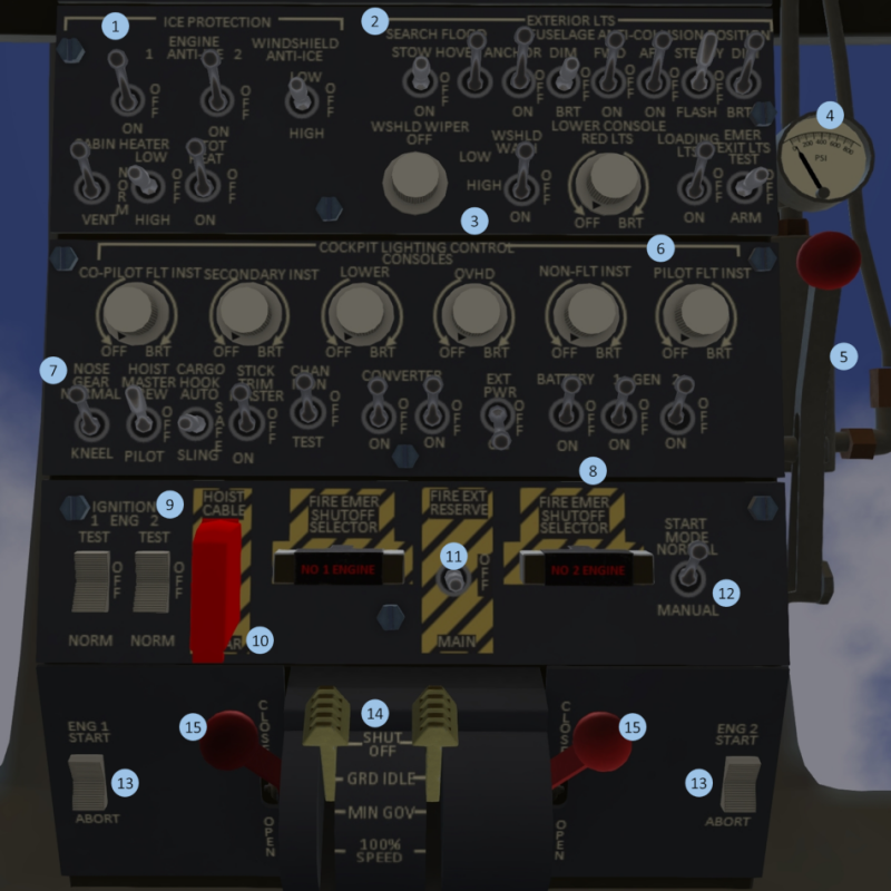
1.6 Overhead Panel
| 1. Ice Protection | 2. Exterior Lighting | 3. Windshield Wiper/Wash | 4. Rotor Brake Press. |
| 5. Rotor Brake | 6. Interior Lighting | 7. System Master Switches | 8. Electrical Systems |
| 9. Ignition | 10. Hoist Cable Shear | 11. Fire Protection | 12. Start Mode |
| 13. Starter | 14. Engine Control | 15. Emergency Throttles |
1.7 Middle Panel
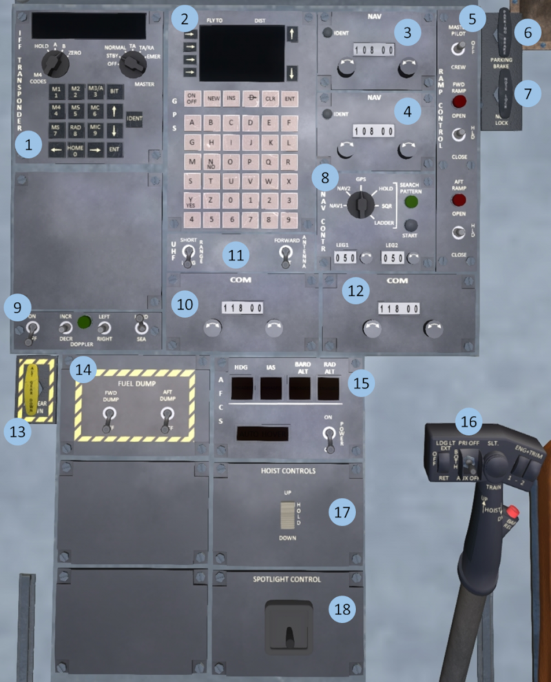
| 1. IFF Trasponder | 2. GPS Panel | 3. #1 NAV Radio | 4. #2 NAV Radio |
| 5. Rear Ramp Control | 6. Parking Brake | 7. Nosewheel Lock | 8. Navigation Control |
| 9. Doppler Panel | 10. Antenna Control | 11. #1 COM Radio | 12. #2 COM Radio |
| 13. Emergency Gear Down | 14. Fuel Dump Panel | 15. AFCS | 16. Hydraulic System Select |
| 17. Hoist Control | 18. Spotlight Control |
1.8 Landing Gear Systems
The S61 has a tricycle type landing gear system with a nosewheel in front and two main gear in sponsons in the back. The gear is hydraulically actuated through the utility hydraulic system. The system includes a squat switch to prevent accidentally raising the gear while the helicopter is on the ground.
1.8.1 Landing Gear Panel
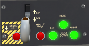
The landing gear panel (see Figure 6) is located on the center portion of the main console. Three lights on the right-hand side of the panel illuminate green when the respective gear is down and locked. The gear is controlled by a two position lever with a red "in motion" indicator light. The light illuminate when the landing gear are in motion. A test button labeled "HLD LT TEST" can be pressed to test the "in motion" indicator light. Finally, a DN LCK REL button can be used to override the squat switch allowing gear to be raised while on the ground.
1.8.2 Landing Gear Malfunctions
Normal wear and tear, or damage through a hard landing can cause the landing gear to malfunctions. Malfunctions may affect retracting, lowering or both. When changing the gear position always verify the red "in-motion" light on the handle comes on, then goes out several seconds later. When lowering gear, always verify you get three green lights indicating the gear is down and locked.
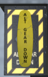
In the event that the gear fails to retract, travel to the next point of landing can be continued, but caution should be used to keep the landing as soft as possible. In the event that gear fails to lower, there is an emergency gear handle (see Figure 7) on the copilot side of the middle console. This handle deploys a compressed air bottle to force the gear into the down position. After use, the air bottle must be replaced before it can be used again. Once the emergency gear extension system is activated, the gear is prevented from retracting until repairs are made to the gear system.
1.8.3 Kneel System
A nose gear kneel switch (see Figure 8) is located on the upper console. This switch is only effective when the landing gear handle is in the down position. Flipping this switch will cause the nose wheel to retract to a 50% retracted position. This can be used to increase the clearance under the tail for loading the helicopter through the ramp. Like the landing gear system, the kneel system requires utility hydraulic pressure to operate.
1.9 Parking Brake
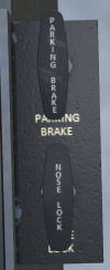
A parking brake (see Figure 9) is located on the pilot side of the middle console. Activating the parking brake will increase resistance to ground movement. Click the handle to toggle its position, or use the chat command:
s brake
to toggle it.
1.10 Nose Wheel Lock
A nosewheel lock (see Figure 9) is located on the pilot side of the middle console just below the parking brake. Activating the parking brake will increase resistance to rotation while on the ground. Click the handle to toggle its position, or use the chat command:
s noselock
to toggle it. The nosewheel lock should be used during rotor engagement to prevent the helicopter from turning on the ground during the high-torque stages of engagement.
2 Emergency Equipment
2.1 Engine Fire Detection System
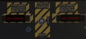
The S61 is equipped with fire sensors and two fire extinguisher bottles to detect and mitigate engine fires. The fire detection system for the #1 and #2 engines is power by the #1 and #2 AC bus, respectively. The fire detection panel is located on the upper console behind the throttle quadrant (see Figure 10). The panel has two fuel cut-off handles for each engine. The handles will light up when a fire is detected (if AC power is available). Pulling a handle will cut off fuel to an engine through a mechanical linkage.
The fire extinguishers are activate by a 3-position toggle switch between the fuel cut-off handles. The switch will have no effect except when a handle is pulled. This switch should normally be left in the middle OFF position. When deploying an extinguisher, first pull the cut-off handle for the affected engine, then switch the FIRE EXT switch to MAIN. This will deploy the bottle corresponding to the affected engine (#1 bottle for #1 engine, #2 bottle for #2 engine). If a single bottle is insufficient to extinguish a fire, you can switch the FIRE EXT switch to the RESERVE position. This will deploy the bottle from the opposite engine (#2 bottle for #1 engine, or #1 bottle for #2 engine). The fire extinguisher bottles are single use. Once they have been used, they must be replaced on the ground.
2.2 APU Fire Detection System
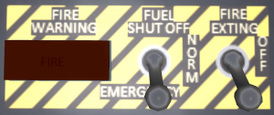
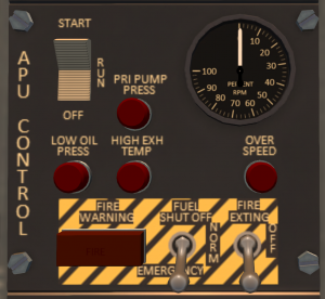
The APU fire detection panel (see Figure 11) is on the APU panel located on the pilot's side panel. The APU fire detection and mitigation system operates off the DC bus. A warning light will illuminate to indicate a fire has been detected. To activate the fire suppression system, flip the FUEL SHUT OFF switch and FIRE EXTING switches to the forward position.
2.3 Fire Warning Test Panel
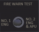
A fire warning test panel is located on the pilot side of the main panel (see Figure 12). The panel contains a three-position switch. Flipping the switch to either side from the center position will test the fire detection system and lights for the indicated systems. When the switch is moved to the left marked NO 1 ENG, the fire detection warning light in the Engine #1 fuel cut-off handle will illuminate. When the switch is moved to the right marked NO 2 ENG & APU, the fire detection warning light in the Engine #2 fuel cut-off handle will illuminate, as well as the warning light for the APU.
2.4 Emergency Lights
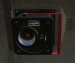
Emergency lights (see Figure 13) are installed at various positions in the helicopter and provide lights for emergency evacuation in the event of a crash. They are controlled by a three position switch labeled EMER EXIT LIGHTS on the pilot-side of the upper console. In the TEST position, all emergency lights will turn on for testing. In the OFF position, the lights will always remain OFF. In the ARM position (recommended for normal flight), the emergency lights will come on in the event of a sudden acceleration or shock. Once the shock sensor has been tripped, it must be manually reset by clicking on one of the emergency lights in the helicopter.
2.5 Emergency Ramp Release
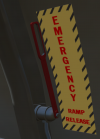
An emergency ramp release (see Figure 14) is located in the rear of the aircraft on the right side near the ramp. Pulling this lever will disconnect the ramp from the hydraulic actuators and allow it to fall by gravity. Click the lever again to reengage the hydraulic actuators and restore normal functioning to the ramp.
3 APU
4 Engines and Related Systems
4.1 General
The S61-R is powered by two General Electric T58-GE-10 turboshaft engines delivering 1,400 shp each. The engines are mounted above the main cabin in front of the main transmission.
4.2 Engine Control Levers
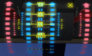
Engine control levers and emergency throttles are located on the forward overhead panel between the pilot and copilot seats. In normal operation, only the yellow engine control levers are used. To operate the levers, click in the general area of the lever to bring up the control overlay (see Figure 16). Once the overlay is active, clicking on one of the scales will move the lever under it to the selected position. To dismiss the control overlay, you can click the "X".
The blue scales in the center part of the overlay are used for the engine control levers. Clicking on one of the one of the wide blue scales will move the lever under it to the selected position. There are stops at "SHUT OFF", "GRD IDLE" (ground idle) and "MIN GOV" (minimum governed) positions. Above "MIN GOV", the engine control lever is analog and can be placed at any position to operate the engine at a specific RPM. A "100% SPEED" marking shows the approximate position for 100% RPM. In normal operations, RPM should be between 90% and 110%.
Next to each engine scale is a narrower "trim" scale. Clicking on the trim scale will nudge the engine control in the indicated direction relative to the center point. The further you click from the center point of the scale, the larger the nudge will be.
Between the two throttles is a paired scale. Clicking on this scale will move both engine control levers to the indicated position.
The engine control levers do not directly control the throttles on the engine. Instead they command a fuel controller to maintain a specific RPM. As the load on the engine is increased, the throttle is opened to maintain that RPM.
4.3 Emergency Throttle Levers
On the outside of the engine control quadrant are two emergency throttle levers. In normal operation, they are left in the CLOSED position. In the event of a fuel controller failure, the throttle will "stick" in its position when the controller failed. The emergency throttle levers have a mechanical linkage that allows them to open the throttle beyond the point where it failed, but the throttle cannot be closed through use of the emergency throttles. In practice, the first part of travel of the emergency control lever will have no effect until it is opened beyond the point of the stuck position.
When using an emergency throttle in flight, care should be taken to make collective movements as slow and gradual as possible to avoid overspeeding the engine. Adjustments to the collective or an emergency throttle should always be done while monitoring engine and rotor rpm.
To move an emergency throttle, click on one of the red scales of the engine control overlay. The large scales move the throttle to the selected position, while the smaller scales next to it are for trim, nudging the throttle in the indicated direction.
4.4 Ignition System
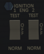
Ignition switches are located on the lower left side of the upper console. There is one three position rocker switch for each engine. The ignition system is powered by the DC bus. In the center OFF position, the engine igniters are deenergized. A spring-loaded TEST position for each rocker can be used to test the igniters. When held in the TEST position with DC power active, a clicking sound will be heard. The igniters should never be tested except when the engine control levers are in the SHUT OFF position, the starters are not running, and the engine fuel values are closed. In the NORM position, the igniters will activate while the starter is running. This position should be used for normal start and while engine is operating.
WARNING: Do not advance engine control levers out of SHUT OFF with the igniters active until N2 is above 20%.
4.5 Starter System
Each engine is equipped with an electric starter powered by the DC Bus. The starter is activated by a three-position rocker switch on the upper console, one for each engine (see Figure 18). To engage the starter, momentarily move the switch to the START position. The switch is spring loaded an will return to the center position, but the starter will continue to run. The starter will turn the compressor stage (N1) of the engine up to 26% to allow normal flow of fuel and air for an engine start. Pressing the ABORT side of the starter switch will disengage the starter motor.
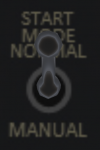
When the start mode switch (see Figure 19) is in the NORMAL position, the starter will automatically dropout when N1 exceeds 35% as the engine spins up during start. Placing the start mode switch in the MANUAL position will disable this behavior.
The electrical field from the starter motor will cause a change in the heading indicated on the magnetic compass. For this reason, it is suggested that the crew note the magnetic compass heading before engaging the starter so that they can confirm the starter dropout occurs at 35% N1. This change in the compass is the only way to know that starter dropout has occurred.
4.6 Primary Engine Instruments
| Gauge | Description |
|---|---|

|
N2 |
|
Torque |
4.7 Secondary Engine Instruments
| Gauge | Description |
|---|---|

|
N1 |

|
TIT |

|
Oil Pressure |

|
Oil Temperature |
4.8 Engine Warnings/Alerts
Alert #1 ENG OIL QTY LOW
4.9 Engine Operating Limitations
5 Fuel System
5.1 Fuel System Overview
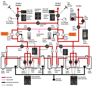
The S61R has two independent pressure-type fuel systems (see Figure 20) joined with a crossfeed connection. Each system (forward and aft) consists of a main tank and an auxiliary tank (four total tanks). The forward system feeds the #1 engine, while the aft system feeds the #2 engine. Boost pumps and transfer valves can be used to transfer fuel from the auxiliary to the main tanks. Each system has two boost pumps submerged in the main tank, and a third unboosted feed line. The engines also contain their own engine-driven fuel pump which can draw fuel on its own from the main tanks. An electrically operated crossfeed valve can be opened to allow crossfeed of fuel from one system to the opposite engine.
5.2 Fuel Tanks
The S61R is equipped is equipped with the following four fuel tanks having the following capacities:
| Tank | Capacity | Feeds |
|---|---|---|
| Forward Tank | 348 gal. | Feeds #1 engine |
| Aft Tank | 345 gal. | Feeds #2 engine |
| Forward Aux Tank | 184 gal. | Feeds Forward and Aft tanks |
| Aft Aux Tank | 245 gal. | Feeds Aft Tank |
Each fuel tank can be refueled using either a gravity filler or through the pressure refueling system.
5.3 Fuel Type
The S61R is designed to operate on JP-5 or JET-A fuel. When refueling with KellyFuel 3.0 or later, care must be taken to use the correct fuel type. If the incorrect fuel type is used, the fuel in that tank will be tainted, and operating the engine with tainted fuel will cause engine damage. If a tank is accidentally filled with the wrong type of fuel, the tank must be completely emptied to flush it of all contaminant. The tanks can be flushed either using the fuel dump system, or through the @Cheat menus.
5.4 Fuel Booster Pumps
Two fuel booster pumps are located in each main tank. The booster pumps are located in a collector can located in each tank. As fuel is pumped to the main engine, it is also pumped back to the main tank through an ejector unit to ensure the collector can remains full. Ejector units in the auxiliary tanks, which are activated by opening an electrically controlled valve, allow the boost pumps to transfer fuel to the main tanks.
The pumps for each tank use a different power source. In the forward system, the No 1 boost pump is powered by the #1 AC bus, and the No 2 boost pump is powered by the #1 AC Monitor Bus. In the aft system, the No 1 boost pump is powered by the #2 AC bus, and the No 2 boost pump is powered by the #2 AC Monitor Bus.
The pumps are controlled by switches on the fuel system control panel. Each pump has a low pressure indicating light above it. The indicator light is active only then the pump switch is turned on. When turning on a pump, the indicator light should flicker briefly, then go out. If the low pressure warning light remains on, it indicates the pump has failed, or is not receiving AC power from the appropriate system.
Engine may be operated with one, both or no boost pumps. However, boost pumps must be used in the following conditions:
- Above 6000 feet MSL.
- While dumping fuel
- Above 43 degrees C
- While transferring fuel
- When below 600 pounds of fuel per tank.
- Whenever a fuel filter by-pass light is illuminated
- One pump per tank during takeoff and landing
- During crossfeed operations
Note: Continuous operation of at least one boost pump per engine is recommended to prevent inadvertent operation of the aircraft during one of the above conditions.
5.5 Fuel System Control Panel
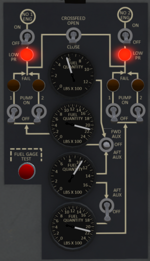
The fuel system is controlled through a fuel management panel (see Figure 21) mounted in the center portion of the main control panel.
5.5.1 Fuel Gauges
Fuel gauges for each tank are located on the center of the fuel management panel. From top to bottom the gauges are for the forward auxiliary, forward main, aft auxiliary and aft main tanks. The forward main, and aft auxiliary tank fuel gauges are powered by the #1 AC Bus, while the aft main and forward auxiliary gauges are powered by the #2 AC Bus.
5.5.2 Fuel Gauge Test Button
A red fuel gauge test button is located in the lower left corner of the fuel management panel. Press and hold this button cause all four gauges to go to a zero reading. Releasing the button will cause the gauges to return to the actual reading if they are powered and functioning correctly.
5.5.3 Fuel Shutoff Switches
At the top of the panel are two fuel shutoff valves. The shutoff switches are located below the NO 1 ENG and NO 2 ENG labels and operate electrically controlled shutoff valves.
5.5.4 Low pressure warning lights
Below the shutoff switches are two low pressure lights. The lights will illuminate when there is inadequate fuel pressure to their respective systems.
5.5.5 Boost Pump Switches
A pair of boost pump switches along with their associated low-pressure warning lights are located on each side of the fuel tank gauges. The switches on the left side are for the forward system, while the switches on the right side are for the aft system.
5.5.6 Fuel Transfer Switches
Two fuel transfer switches are located to the right of the fuel gauges. The transfer switches operate an electrically controlled valve that allows the boost pump for the tank to which fuel is flowing to force fuel from the selected auxiliary tank into that main tank. The top fuel transfer switch is three-position and can be set to transfer fuel from either the forward auxiliary to the forward main tank. The lower fuel transfer switch can be set to transfer fuel from the aft auxiliary tank to the aft main tank.
5.5.7 Crossfeed Switch
In the top center of the fuel management panel is the crossfeed switch. This switch controls an electrically controlled crossfeed valve. This switch can be used to feed an engine from the opposite fuel system. The boost pumps from the system feeding the opposite engine must be on when conducting crossfeed operations.
5.6 Low Fuel Caution Lights
The low fuel caution lights FWD FUEL LOW and AFT FUEL LOW are located on the caution and advisory panel on the main control panel. These lights will illuminate when 170-280 pounds remain in the respective main tanks. The caution lights operate off DC power. When a light illuminates, it is recommended that the pilot land as soon as practicable to refuel, or that fuel be transferred from the auxiliary tanks. Prolonged operation with a blocked filter is not recommended as it will allow unfiltered fuel to flow through the fuel control and engine, leading to possible damage to those components.
5.7 Fuel Filter By-Pass Caution Lights
The fuel-filter by pass caution lights marked FWD FUEL BY-PASS and AFT FUEL BY-PASS are located on the caution and advisory panel on the main control panel. The caution lights illuminate when the fuel filter by-pass value in the respective system is open and fuel is by-passing the fuel filter. This light indicates blockage in the fuel filter and that the filter should be replaced.
5.8 Gravity Refueling
Gravity refueling ports are located on the left side of the aircraft in front of the left sponson. The forward auxiliary and tank fillers are located behind separate panel doors, while the aft auxiliary and main tank fillers are located behind a shared panel door. To refuel a tank through the gravity refuel system, the panel door must be open and the tank cap must be removed by clicking on them. Tanks can be filled using either KellyFuel or by using the "refuel" chat command.
The front strut can be used as a ground point while refueling. Always properly ground your aircraft before fueling to avoid a static discharge from sparking a potential fuel fire.
5.9 Pressure Refueling
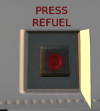
The pressure refueling port behind a panel door on the right side of the aircraft below the main cabin door. Open the panel door and undo the cap on the fuel port to prepare for fueling. Pressure refueling can be used to more rapidly refuel all tanks of the aircraft at once. Fuel flow rate while pressure refueling is approximately 10 times the rate as with gravity refueling. The pressure refueling system is compatible with KellyFuel. You can also use the "refuel" chat command while a cap is open.
The front strut can be used as a ground point while using the pressure refueling system. Always properly ground your aircraft before fueling to avoid a static discharge from sparking a potential fuel fire.
5.10 Fuel Dumping
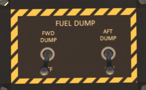
The S61 is equipped by a fuel dump system to dump fuel in flight from the main tanks. The dump system is controlled through the fuel dump control panel shown in Figure 24. The fuel dump switches control electric gate valves located off the fuel line ahead of the fuel filter. When conducting a dump, at least one boost pump in the target tank must be operating. Fuel can only be dumped from the main tanks. To dump fuel from an auxiliary tank, the fuel must first be transferred from the auxiliary to the main tank. Dumped fuel is expelled through a tube located at the back of the right sponson. The dump system is capable of dumping 140 pounds/min from each side.
6 Flight Controls and AFCS
6.1 Flight Controls
The helicopter is controlled by changing the pitch of the blades collectively or cyclically. Pitch changes are made through the flight controls which include a collective, a cyclic control stick and anti-torque pedals. The pilot and copilot controls are interconnected and move together. The collective increases the pitch of all blades, controlling the helicopter vertically. The anti-torque pedals control the pitch of the tail rotor, thus changing the tail rotor thrust. The cyclic imparts unequal pitch around the blade disk to redirect thrust laterally or longitudinally. See SECTION 1 - General for details on the Second-Life control options for the controls.
6.2 AFCS
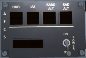
The Advanced Flight Control System (AFCS) can be used to reduce pilot workload by maintaining one or more flight axes of the helicopter. It can be used to maintain airspeed, heading, altitude or any combination of these. The system is comprised of an AFCS computer, a doppler radar system, sensors, channel monitor, an afcs indicator, actuators and a common AFCS control panel (see )
At the top of the AFCS panel are four "hold" buttons. Turning on a hold causes the selected flight axis to be maintained automatically by the AFCS. The following four holds can be maintained:
| Button | Effect |
|---|---|
| HDG | Holds heading. Below 40 knots, heading will be maintained with pedals, and above 40 knots with lateral cyclic. When enaged, the current heading will be held. You can change the heading either through chat command, or by turning the heading bug on the HSI. |
| IAS | Holds the Indicated Airspeed you were maintaining when the button was engaged. The hold airspeed can be changed through chat commands. |
| BARO ALT | Holds the altitude at the time you engaged the hold. Target altitude can be changed through chat commands. |
| RAD ALT | Holds the radar altitude (above ground level) at the time you engaged the hold. Radar altitude can only be used to the limit of the radar altimeter. Target altitude can be changed through chat commands. |
In addition to the hold buttons is an AUTOHOVER button at the bottom of the AFCS panel. Engaging AUTOHOVER will set holds on heading, airspeed and altitude and set the hold airspeed to zero. Pressing AUTOHOVER again while already in an autohover will disengage the autotpilot.
6.3 AFCS Chat Commands
he following chat commands can be used with the AFCS:
| Command | Description |
|---|---|
| ap IAS | Toggle airspeed hold |
| ap ALT | Toggle altitude hold |
| ap RALT | Toggle radar altitude hold |
| ap HDG | Toggle heading hold |
| ap HVR | Enter autohover mode |
| ap DIS | Disconnect autopilot |
| ap IAS n | Set the target airspeed to n |
| ap HDG n | Set the target heading to n |
| ap L n | Set the target heading left by n degrees |
| ap R n | Set the target heading right by n degrees |
| ap ALT n | Set the target altitude to n feet |
| ap RALT n | Set the target altitude to n feet above ground |
| ap D n | Set target altitude up n feet |
| ap U n | Set target altitude down n feet |
| ap to | Take off to a low hover then enter autohover |
| ap land | Autoland aircraft. |
6.4 AFCS Indicator
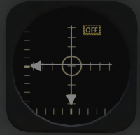
An AFCS indicator gauge (see Figure 26) is mounted on the pilot and co-pilot sides of the main instrument panel. The gauge takes input from the AFCS and displays any movement of the helicopter from a stable hover. The AFCS and doppeler radar systems must be on for the AFCS indicator to function, but the AFCS does not need to be engaged. The vertical and horizontal needles show lateral and longitudinal movement relative to the ground, respectively. When the needles are centered, there is no lateral or longitudinal movement of the helicopter. The more the deflection of each needle, the higher the ground movement is. When a needle is deflected, the cyclic must be moved in the direction of the needle to stop movement of the helicopter.
The triangle indicator on the bottom of the indicatorwith a horizontal scale shows yaw motion. The more the triangle is deflected from the center, the faster the the yaw motion of the helicopter. Press the anti-torque pedal opposite the arrow deflection to stop yaw motion and center arrow.
The triangle indicator on the left side of the indicator with the vertical scale reflects vertical motion of the helicopter. The amount of deflection indicates he amount of vertical movement. Apply collective in the opposite direction of the deflection to recenter the needle and stop vertical movement.
6.5 Channel Monitor Panel
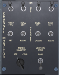
The AFCS outputs commands on four channels: pitch (longitudinal cyclic), roll (lateral cyclic), collective and yaw. The channel monitor panel (see Figure 27, located on the pilot's side console, modulates these outputs and allows information on one or more channels to be disabled in the event of a partial AFCS failure. In normal operation, the channel switches at the top of the panel should all be left in the ON position. Moving a switch to the OFF position will disable output from the AFCS on the indicated channel.
Each channel also has a three-position hardover switch. These switches are normally left in the center OFF position. Moving a hardover switch forward or back will force output on the AFCS channel in the indicated direction.
A channel monitor test switch, located on the upper panel, can be used to test the channel monitor. When the AFCS is on, and the channel monitor test switch is in TEST mode, the control output on each channel will cycle back and forth slowly over a small displacement. Turnning off a channel switch will stop movement on the affected channel.
The channel monitor panel also includes a switch labeled VERTICAL GYRO. The vertical gyro is used to send pitch and roll information to the AFCS. The helicopter is equipped with a port and a starboard gyro. In the event one of these gyros fail, use this switch to select the other gyro.
A METER SELECTOR knob can be used to select the information that is displayed on the AFCS indicator. In normal operation only the ASE position should be used.
6.6 Doppler
The autopilot/AFCS gets its lateral movement information through a doppler radar system. The doppler system is controlled by a panel (see Figure 28) on the middle console. A green indicator light on the doppler panel shows when the system is powered and functioning. In additional the doppler system has the following four switches:
| Switch | Description |
|---|---|
| ON/OFF | Turns the unit on and off. |
| INCR/DECR | Test switch for longitudinal motion sensing. When in the INCR or DECR positions, a constant "forward motion" or "backward motion" signal will be sent to the AFCS. In normal operation this switch should be in the center position. |
| LEFT/RIGHT | Test switch for lateral motion sensing. When in the LEFT or RIGHT positions, a constant "left motion" or "righ motion" signal will be sent to the AFCS. In normal operation this switch should be in the center position. |
| LAND/SEA | This switch controls the sensing mode of the doppler system. When LAND is selecting, motion sensing is optimized for land operation. When SEA is selected, motion sensing is optimized for over-water operations. If the switch position does not correspond to the type of surface the helicopter is flying over, AFCS hover performance over that surface will be degraded. |
7 Hydraulic Systems
7.1 General
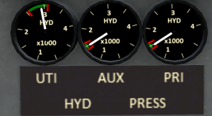
The S-61R has two flight control hydraulic systems (primary and auxiliary) and a utility hydraulic system. All hydraulic pumps are powered by the main transmission accessory drive which is powered by either engine or by the APU. Engine and/or APU must be at above 70% RPM for hydraulic pressure to be available. A bank of three pressure gauges shows the pressure of each system (see Figure 29).
7.2 Flight Control Hydraulics
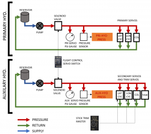
The primary and auxiliary hydraulic systems (see Figure 30) provide boost power to operate the flight controls. The flight servos also limit feedback of vibration in the rotor system to the flight controls. These act in conjunction with the direct linkages from the flight controls to the swash plate to reduce the forces needed to actuate the controls. Each system operates independently and operates a similar set of servos. In normal operation, both systems are in use during flight, but a switch on the collective can be used to disable either system in the event of a hydraulic failure on one of the systems.
7.2.1 Primary Hydraulic System
The primary hydraulic system powers three hydraulic servo units that control the main rotor swash plate for cyclic and collective control inputs. The primary hydraulic system does not provide any boost or damping for the anti-torque pedals. A low pressure sensor detects when the hydraulic pressure is inadequate and illuminates a PRI-HYD PRESS warning light on the warnings and alerts panel. A pressure gauge on the main panel also shows the pressure available in the system. The primary hydraulic system is feed by a 0.45 gallon reservoir located in the rear portion of the engine and transmission compartment.
7.2.2 Auxiliary Hydraulic System
The auxiliary hydraulic system powers four hydraulic servo units, three that control the main rotor swash plate for cyclic and collective control inputs, and a fourth servo unit driving the anti-torque pedals. The auxiliary system also handles cyclic trim and the AFCS. A low pressure sensor detects when the hydraulic pressure is inadequate and illuminates a AUX-HYD PRESS warning light on the warnings and alerts panel. A pressure gauge on the main panel also shows the pressure available in the system. The auxiliary hydraulic system is feed by a 0.45 gallon reservoir located in the rear portion of the engine and transmission compartment. Note that the auxiliary hydraulic system must be functioning for AFCS use.
When the auxiliary hydraulic system is active, and the STICK TRIM MASTER switch on the overhead console is ON, the following fine control chat commands are enabled:
| Command | Description |
|---|---|
| fc | Toggles fine control on/off. |
| fc0 | Turns off fine control. |
| fc1 | Turns on fine control. |
| fc2 | Turns on very fine control. |
7.3 Utility Hydraulic System
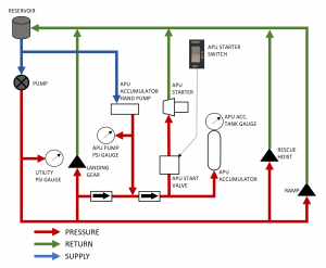
The utility hydraulic system (see Figure 31) provides pressure to all hydraulic systems other than the flight controls. A 3000psi pump drives the system. Hydraulic fluid is held in a 5.03 quart reservoir located in the aft of the engine and transmission compartment. A pressure indicator in the cockpit (see Figure 29) indicates the current pressure in the system.
The utility hydraulic system provides pressure for the following systems:
- Landing gear
- Ramp
- Hoist
- Cargo hook
- APU starter/accumulator
