Difference between revisions of "SL Helicopter Flying Handbook/Aerodynamics"
(→Translational Lift) |
(→Autorotation) |
||
| (6 intermediate revisions by the same user not shown) | |||
| Line 158: | Line 158: | ||
==== Translational Lift ==== | ==== Translational Lift ==== | ||
| + | <div style="clear: both" ></div> | ||
| + | {| style="float: right" | ||
| + | | | ||
[[File:below-etl.png|200px|thumb|right| | [[File:below-etl.png|200px|thumb|right| | ||
<figure id="fig:below-etl"><caption>Flight Below ETL</caption></figure>]] | <figure id="fig:below-etl"><caption>Flight Below ETL</caption></figure>]] | ||
| + | | | ||
| + | [[File:above-etl.png|200px|thumb|right| | ||
| + | <figure id="fig:above-etl"><caption>Flight Above ETL</caption></figure>]] | ||
| + | |} | ||
| − | When a helicopter is in a hover or at a low speed, airflow through the disk is at a right angle to the rotor plane, and the rotors must provide all induced airflow through the rotors. Additionally, some of the flow recirculates through the rotor system as show in <xr id='fig:below-etl'/>. | + | When a helicopter is in a hover or at a low speed, airflow through the disk is at a right angle to the rotor plane, and the rotors must provide all induced airflow through the rotors. Additionally, some of the flow recirculates through the rotor system as show in <xr id='fig:below-etl'/>. As a helicopter accelerates, it moves out of this downward moving/recirculating air and experiences a significant increase in performance. |
| − | + | ===== Effective Translational Lift (ETL) ===== | |
| − | + | At approximately 15-20 knots, the helicopter completely overtakes the recirculating air and moves into clean air (<xr id='fig:above-etl'/>). This is referred to as Effective Translational Lift (ETL). As a helicopter passes through ETL, it requires significantly less power to maintain altitude, and more power is available for climbs. This is also the reason that less power is required in cruise flight than for hovering. It is also part of the reason that a normal takeoff involves a short ground run to accelerate past ETL before climbing out. | |
| − | |||
| − | < | ||
| − | |||
| − | |||
| − | |||
=== Autorotation === | === Autorotation === | ||
| + | |||
| + | [[File:Autorotation.png|right|thumb| | ||
| + | <figure id="fig:Autorotation"><caption>Blade Regions During Autorotation</caption></figure> | ||
| + | ]] | ||
| + | |||
| + | In autorotation, the blades of the helicopter are kept turning by airflow moving up through the rotor system, rather than by engine power. Autorotation allows a helicopter to land safely in the event of an engine failure. A freewheeling unit, or sprag clutch, allows the main rotor blades to continue turning without power from the engine. This is similar to the way a bicycle can coast without constantly turning the pedals. | ||
| + | |||
| + | Aerodynamically, the rotor disk can be divided into three regions during an autorotation as shown in <xr id='fig:autorotation'/>. The three regions are: | ||
| + | *Driving Region – Airflow accelerates rotors and greatest lift produced. | ||
| + | *Driven Region – Drag works to slow rotors. Some lift produced here. | ||
| + | *Stall Region – Blade is stalled with no lift and only drag produced. | ||
| + | |||
| + | An autorotation is normally entered by fully lowering the collective. In the event of an engine failure, the pilot must be ready to react by quickly lowering the collective before the rotor RPM decays too much. If the reaction is too late and the RPM is allowed to decay, it may not be possible to recover. | ||
| + | |||
| + | Most autorotations are performed with forward speed. The pilot maintains this forward speed, typically around 60 knots, then conducts a flare just before touchdown, followed by lifting the collective to cushion the landing. | ||
Latest revision as of 04:11, 16 August 2021
SECTION 2. Aerodynamics
Contents
1 The Four Forces of Flight
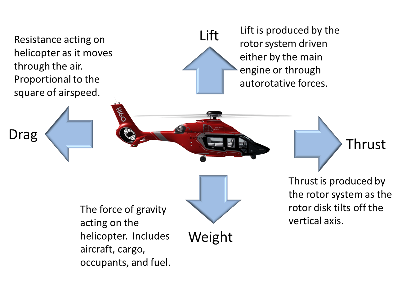
All aircraft are governed by the four force of flight (Figure 1): lift, weight, drag and thrust. When the opposing forces balance each other (lift against weight and thrust against drag) the aircraft will continue with in the same direction and velocity without acceleration. When two opposing forces are different, the aircraft will accelerate until it reaches equilibrium. It is the job of the pilot to control these forces in a way that results in a desired outcome.
Here is a closer look at the four forces in a helicopter:
- Weight - Weight is the force of gravity acting downward. Weight directly opposes lift and is constantly changing during flight as fuel is burned.
- Lift - Lift is produced by the main rotor system(s) and directly opposes weight. Lift is affected by multiple factors including the angle of attack of the rotor blades, the density of the air, the speed of air over the airfoil, etc.
- Thrust - Thrust is the horizontal force, usually in the forward direction, but for a helicopter, can be potentially in any direction. Thrust is controlled by angling the rotor disk so that a portion of the total thrust of the rotors is in a horizontal direction. Thrust directly opposes drag.
- Drag - Drag is the force that is produced by an object moving through the air. Drag is a result of air pushing against the body and all parts of the aircraft. Drag directly opposes thrust.
2 Lift
Every object in the atmosphere is surrounded by a has that exerts a static force of 2,116 pounds per square foot at sea level. When a rotor blade is not moving, that force is exerted equally over the entire blade surface, and thus no useful lift is produced. In a helicopter, this is done by forcing air over the blades through their rotation around a mast.
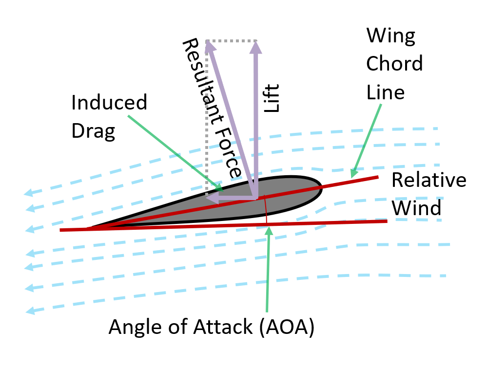
Figure 2 shows how lift is produced by an airfoil as it moves through the air. Lets take a look at some of the elements in the production of lift:
- Relative Wind – Direction of movement of the air relative to the airflow. Usually opposite to the direction of movement.
- Wing Chord Line – The Line from the leading edge to the training edge of the wing.
- Angle of Attack (AOA) – The angle between the relative wind and the wing chord line. In a helicopter, raising the collective generally increases the AOA of the rotor blades.
- Resultant Force – The force acting on the airfoil as it moves through the air.
- Lift – The vertical component of the resultant force. Increases as AOA or the airspeed increases.
- Induced Drag – The horizontal component of the resultant force. Increases as AOA or the airspeed increases. A byproduct of lift that must be overcome by thrust in level flight. In a helicopter, induced drag is what results in the increased engine power required to maintain RPM as the AOA is increased.
More specifically, the lift produced by an airfoil (e.g., a rotor blade) is governed by the Lift Equation:
L = CL(1/2)ρv2S
The components of this equation are:
- L - Total lift produced by the airfoil
- CL - The coefficient of lift
- ρ - The density of the air
- v - The speed of air over the airfoil
- S - The surface area of the airfoil
The coefficient of lift is generally a function of the profile (edge view) of the airfoil, and the angle of attack. CL typically increases linearly with angle of attack up to a specific critical angle of attack. Once the critical angle of attack is exceeded, the coefficient of lift decreased rapidly as the airfoil enters aerodynamic stall.
3 Drag
Drag is the force that resists the helicopter and/or rotor blades as the move through the air. Drag must be overcome by the engine to turn the rotor. Drag always acts parallel to the relative wind and total drag is comprised of three types of drag: profile, induced and parasite.
3.1 Profile Drag
Profile drag is a mix of skin friction and form drag that results from turbulent airflow that is created as a structure moves through the air. Profile drag is a function of the smoothness of a surface, and the size/shape of the structure that protrudes into the relative wind. It is generally weakly correlated with airspeed.
3.2 Induced Drag
Induced drag is generated by airflow circulation around the rotor blade as it creates lift. When an airfoil creates lift, some of the air is forced downward meaning that the relative wind is angled slightly above the horizontal plane. This results in a force that tends to slow the blades that increases as the angle of attack increases (i.e., with increased collective). Induced drag is the main reason that more engine power is required as collective is increased.
3.3 Parasite Drag
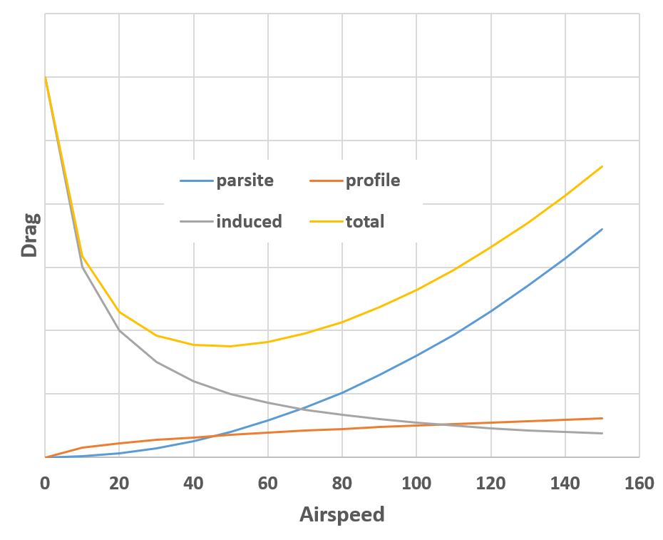
Parasite drag is the drag produced by all the non-lifting surfaces as the helicopter moves through the air (i.e., cabin, rotor mast, tail, landing gear). Parasite drag generally increases as the square of the the airspeed, thus doubling airspeed results in a 4x increase in drag. This means that a 4x increase in thrust is required to achieve a 2x increase in speed.
3.4 Total Drag
Total drag is the total of profile, induced and parasite drag (see Figure 3). Since induced drag decreases with airspeed, while parasite drag increases, there is generally an airspeed at which the lift-to-drag ratio is minimized. This point is referred to as L/DMAX and typically defines the best climb airspeed of the aircraft. In the example shown here L/DMAX is approximately 50 knots meaning 50 knots would be the best climb speed.
4 The Rotor Disk
4.1 Relative Wind
There are two parts to the relative wind as it passes through the rotor system:
- Horizontal part - caused by the blade moving through the rotor plane consisting of the speed of the rotating blade plus the forward airspeed.
- Vertical part - caused by air being moved down through the rotor system, plus any vertical movement of the helicopter. The vertical component is generally larger at slow airspeed.
4.2 Induced Flow
As the pitch of the rotor blades increase, more air is forced down through the rotor system. This induces an downward flow of air which when combined with the horizontal motion of the blade through the air results in a relative wind that is angled downward relative to the path of the blade. This results in a decreased angle of attack, and this less lift. Induced flow is greatest during hover in no-wind conditions.
4.2.1 Ground Effect
Proximity to the ground (land, water, or over a prim) interrupts the downward movement of air, thus reducing the effect induced flow. The effect increased the closer your are to the surface, and diminishes as you increase height over the surface. Ground effect decreases the power needed to hover.
4.2.2 In Ground Effect (IGE) Hover
Hovering near a surface is referred to as an IGE (In Ground Effect) hover. Ground effect permits the relative wind over the rotor blades to be more horizontal thus increasing their efficiency. Ground effect is increased when hovering over smooth surfaces, and decreased over grasses and other rough surfaces.
4.2.3 Out of Ground Effect (OGE) Hover
When hovering outside the range of ground effect (generally above a rotor diameter), the helicopter is said to be in an Out of Ground Effect (OGE) hover. Since you lose the benefits of ground effect in an OGE hover, it requires more power to maintain altitude. At high density altitudes, or in helicopters with less power, it may not be possible to maintain an OGE hover in some cases. Performing an OGE hover also presents the risk of entering vortex ring state if the helicopter is allowed to descend at too great a speed. See #VORTEX RING STATE for more information on vortex ring state.
5 Hovering Flight
Hovering is the most challenging part of flying a helicopter. This is due to the fact that the helicopter is inherently unstable and constant control inputs are needed to maintain a hover. Furthermore, all of these control movements interact with each other such that moving any one control usually requires moving another control as well. That said, the basic principle is relatively simple. The cyclic is used to eliminate horizontal drift, the pedals are used to maintain directional control, and the collective is used to maintain a constant height above the ground.
5.1 Translating Tendency
The primary purpose of tail rotor is to counteract torque from the main rotors. However, a side effect of this is a slight sideward force that would push the helicopter to the right if left uncorrected. This is referred to as "translating tendency" and is illustrated in Figure 4. The counter-clockwise rotating main rotor induces a torque trying to turn the helicopter to the right. The tail rotor pushes air through it to the left, thus creating a thrust to the right. Since this thrust is away from the center of gravity, this causes a counter-clockwise torque (balancing against the torque from the main rotor), and a horizontal component that acts to push the helicopter to the right.
To compensate for translating tendency, the controls on the helicopter are often rigged so that there is a slight left tilt of the main rotor when the cyclic controls are centered. This left force from the main rotor balances the right force from the tail rotor. A side effect of this is that the left skid will hang slightly lower then the right one in a hover.
5.2 Pendular Action
Since the helicopter is suspended from a single point well above the center of mass, it can have a tendency to rock like a pendulum. This is called pendular action and can be exaggerated by poor control technique. When a pilot begins overcontrolling, the pendular action can rapidly increase causing the helicopter to rapidly depart controlled flight. For this reason, it is important for the pilot to use small and smooth control inputs when flying a helicopter.
5.3 Gyroscopic Precession
The spinning blades of a helicopter act like a gyroscope. One of the properties of gyroscopes is gyroscopic precession. Gyroscopic precession causes a spinning object to act 90 degrees in the direction of rotation from where a force is applied. For this reason, the controls on a helicopter are rigged such that the greatest blade pitch occurs 90 degrees before the highest point of the rotor disk.
As an example, consider a helicopter with counter-clockwise rotating blades. Pushing forward on the cyclic will cause the highest blade pitch to occur at the 9 oclock position on the left side of the helicopter. Gyroscopic precession will cause the back of the rotor disk at the 6 oclock position to tilt up, this vectoring some of the thrust in the forward direction.
5.4 Torque
In single main rotor helicopters, torque is produced by the main rotor whenever the helicopter is under power. In most aircraft, the main rotor turns counter-clockwise when viewed from above, resulting in the body of the helicopter having a tenancy to turn clockwise (to the right) the more power you use. As a result, the pilot must apply right pedal to compensate. This is particularly evident when pulling collective to lift into a hover which requires the most amount of power. Conversely, right pedal must be applied when reducing power/collective. A few aircraft (e.g., Russian and French) have main rotors that turn clockwise when viewed from above. In these aircraft, the effect is reversed and left pedal is needed to compensate as collective is increased.
In aircraft with tandem rotors such as the Chinook, or in aircraft with coaxial rotors such as the Hiller UH-4, the rotors are counter-rotating and thus torque is canceled.
6 Forward Flight
In straight-and-level, unaccelerated forward flight, lift equals weight and thrust equals drag. If lift drops below weight, the helicopter will descend until the forces are in balance again. The same will occur if lift increases above weight. Similarly if thrust increases above drag, forward airspeed will increase thus increasing drag until it exactly balances the new higher thrust.
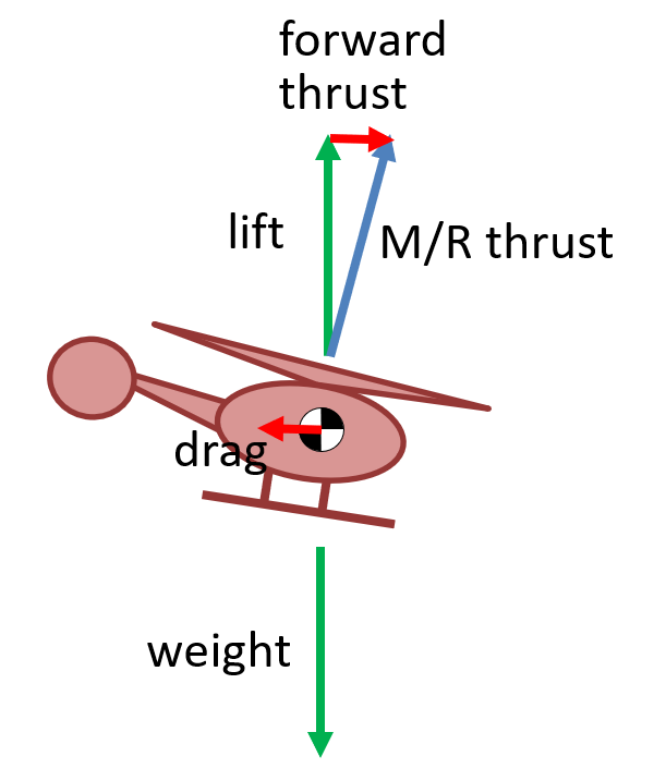
Figure 5 shows the four forces of a helicopter in forward level flight at constant speed. When the rotor disk tilts forward, the total main rotor thrust (shown by the blue line) is angled forward perpendicular to the rotor disk. In this state, the main rotor thrust can be decomposed into a vertical (green) and a horizontal (red) component. Since we are in level unaccelerated flight, we know that the vertical component (i.e., lift) must equal weight, and the horizontal component (thrust) must equal drag.
As the rotor disk tilts forward more, the horizontal component increases resulting in higher forward airspeed. But since the lift must equal weight in order to maintain altitude, it is necessary to increase the main/rotor thrust as this happens. This is normally done with increased collective and is why more collective is required as forward speed is increased.
6.1 Airflow in Forward Flight
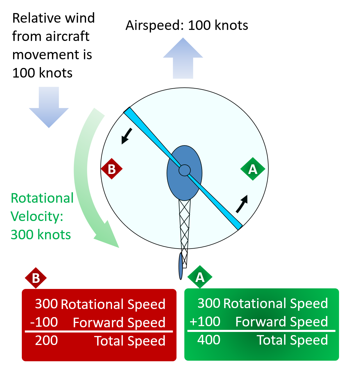
In forward flight, the forward speed of the aircraft combines with the rotor tip speed to determine the speed of the relative air seen around the rotor disk. For example, consider the situation shown in Figure 6. In this example, the airspeed at the rotor tip in a hover is 300 knots, and the aircraft is moving forward at 100 knots. Since the aircraft is moving forward at 100 knots, there is a 100 knot relative wind from the opposite direction. Assuming a helicopter with counter-clockwise rotating blades, the blade on the right side at point A (called the "advancing blade") is moving forward into the relative wind, so the net relative wind it see will be the 300 from its rotation, plus the 100 from the oncoming air from forward motion. This results in a 400 knot relative wind at the blade tip at point A. On the left side of the rotor disk at point B (called the "retreating blade"), the blade is moving backwards. The relative wind seen by the blade at point B will be the 300 knots from the blade rotation, minus the 100 knots for the forward speed. This means the relative wind at point B will be 200 knots.
6.1.1 Dissymmetry of Lift
Dissymmetry of Lift is the apparent unequal lift on the two sides of the rotor disk in forward flight due to the unequal airflow over each half of the disk. Referring back to the example in Figure 6, we see that the advancing blade sees a relative wind of 400 knots, while the retreating blade sees a relative wind of 200 knots. Recall from Section 2.2 - Lift, that lift is proportional to the square of the relative wind. Since the relative wind on the advancing blade is double that on the retreating blade, that would suggest the lift on the right side of the rotor disk should be 4 times that on the left side. If this were true, the helicopter would roll violently to the left as forward speed were increases. Since this does not happen, there must be some other mechanism at play.
What is actually happening, is blade flapping. A hinge at the rotor hub, called the flapping hinge, allows each blade to move up and down. Blades will flap up on the advancing side, and down on the retreating side. The upward motion of the blade on the advancing side causes the angle of attack on that side to decrease, thus reducing the lift. Similarly, the downward motion on the retreating side increase the angle of attack, this increasing the lift on that side. The flapping of the blades allow the forces to balance exactly, equalizing the lift around the rotor disk. This normally happens automatically without any input from the pilot.
6.1.2 Retreating Blade Stall
As the speed of the helicopter increases more, the relative wind over the retreating blade becomes smaller and smaller. At some point, there will not be enough airflow over the retreating blade to maintain lift, and the blade will stall. This is called retreating blade stall. When the aircraft enters retreating blade stall, it will begin to lose lift and roll, sometimes violently, to the left. The pilot must react quickly with aft cyclic to reduce the airspeed and stop the stall. Retreating blade stall is what generally determines the never exceed speed (Vne) in helicopters and is usually marked with a red line on the airspeed indicator. The pilot should not that the red line represents Vne at sea level. The never exceed speed generally decreases with altitude.
6.2 Translational Lift
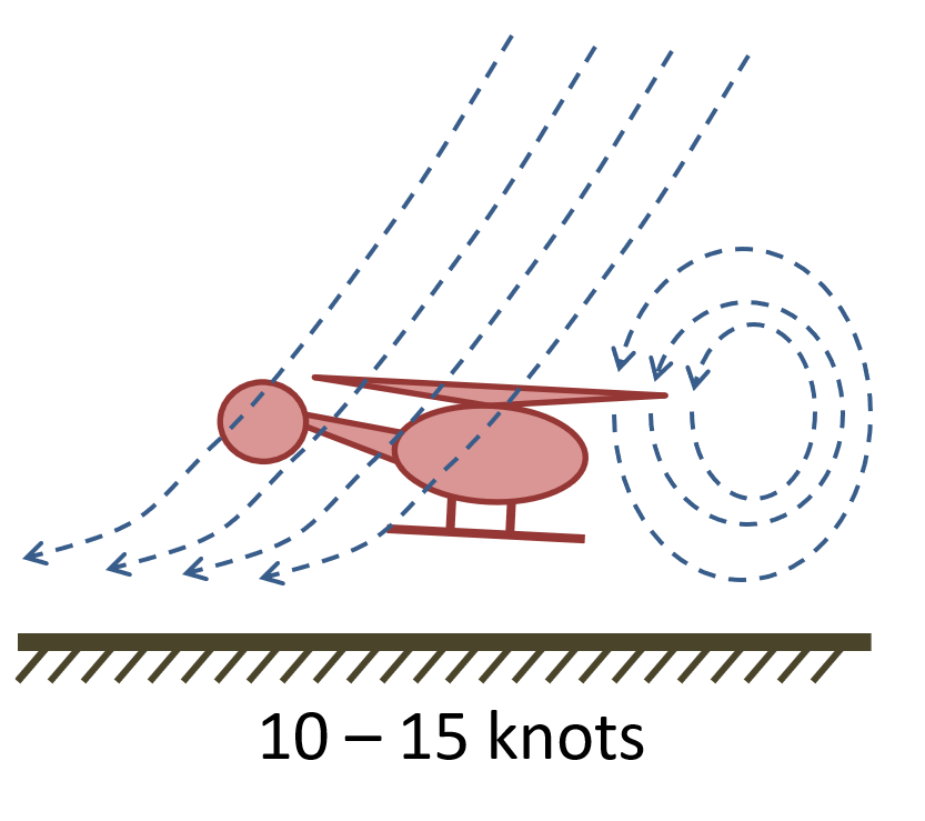
When a helicopter is in a hover or at a low speed, airflow through the disk is at a right angle to the rotor plane, and the rotors must provide all induced airflow through the rotors. Additionally, some of the flow recirculates through the rotor system as show in Figure 7. As a helicopter accelerates, it moves out of this downward moving/recirculating air and experiences a significant increase in performance.
6.2.1 Effective Translational Lift (ETL)
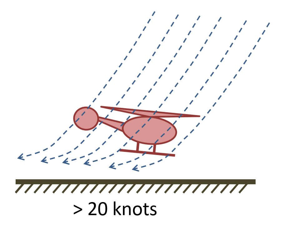
At approximately 15-20 knots, the helicopter completely overtakes the recirculating air and moves into clean air (Figure 8). This is referred to as Effective Translational Lift (ETL). As a helicopter passes through ETL, it requires significantly less power to maintain altitude, and more power is available for climbs. This is also the reason that less power is required in cruise flight than for hovering. It is also part of the reason that a normal takeoff involves a short ground run to accelerate past ETL before climbing out.
7 Autorotation
In autorotation, the blades of the helicopter are kept turning by airflow moving up through the rotor system, rather than by engine power. Autorotation allows a helicopter to land safely in the event of an engine failure. A freewheeling unit, or sprag clutch, allows the main rotor blades to continue turning without power from the engine. This is similar to the way a bicycle can coast without constantly turning the pedals.
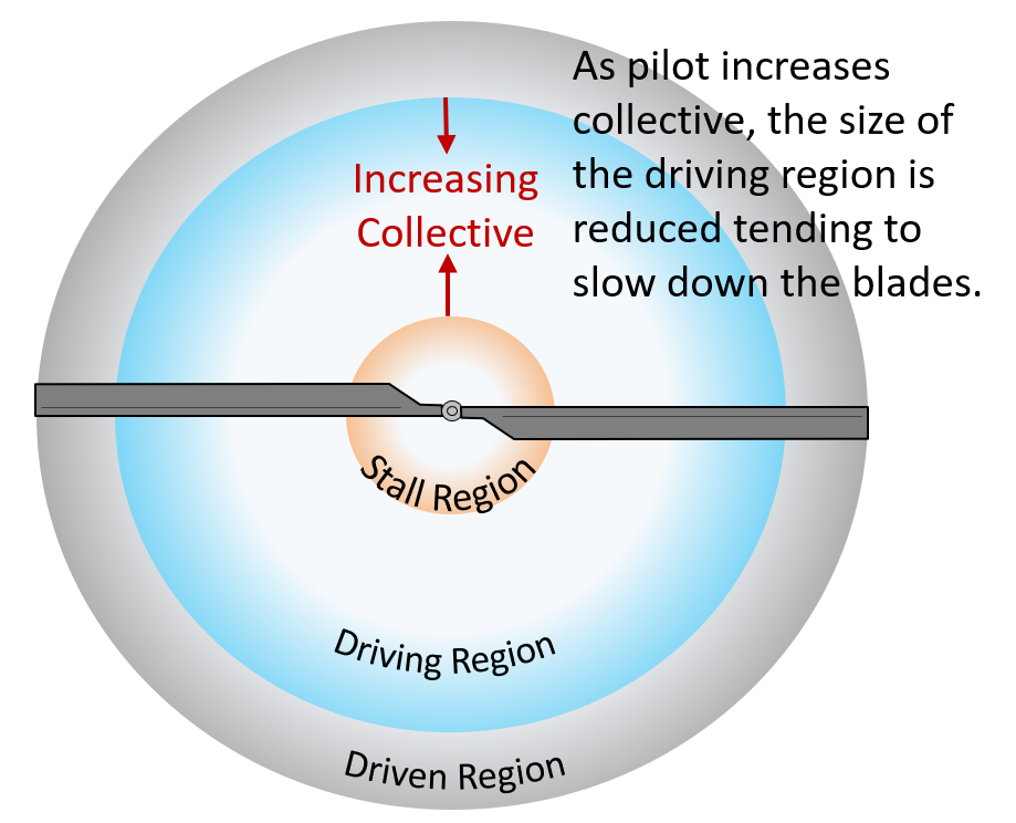
Aerodynamically, the rotor disk can be divided into three regions during an autorotation as shown in ???. The three regions are:
- Driving Region – Airflow accelerates rotors and greatest lift produced.
- Driven Region – Drag works to slow rotors. Some lift produced here.
- Stall Region – Blade is stalled with no lift and only drag produced.
An autorotation is normally entered by fully lowering the collective. In the event of an engine failure, the pilot must be ready to react by quickly lowering the collective before the rotor RPM decays too much. If the reaction is too late and the RPM is allowed to decay, it may not be possible to recover.
Most autorotations are performed with forward speed. The pilot maintains this forward speed, typically around 60 knots, then conducts a flare just before touchdown, followed by lifting the collective to cushion the landing.
