Difference between revisions of "S-61R Pelican/Systems"
(→Master Alert/Caution Panel) |
(→Engine Fuel Control System) |
||
| (51 intermediate revisions by 2 users not shown) | |||
| Line 8: | Line 8: | ||
| − | The Shergood S-61R is a twin-turbine engine helicopter designed for transportation of cargo and for search-and-rescue operations in day, night, visual and instrument conditions. The helicopter is powered by two 1,400 shp General Electric T58-GE-10 turbo-shaft engines mounted above the main cabin in front of the main transmission. Drive shafts from each engine is connected to the main transmission through a mixing unit such that the rotors will continue to spin even if one engine fails. When the rotors are not turning, an APU ( | + | The Shergood S-61R is a twin-turbine engine helicopter designed for transportation of cargo and for search-and-rescue operations in day, night, visual and instrument conditions. The helicopter is powered by two 1,400 shp General Electric T58-GE-10 turbo-shaft engines mounted above the main cabin in front of the main transmission. Drive shafts from each engine is connected to the main transmission through a mixing unit such that the rotors will continue to spin even if one engine fails. When the rotors are not turning, an APU (Auxiliary Power Unit) can be used to supply electrical power and hydraulic pressure. Fuel is carried in compartments in the lower hull of the helicopter with forward and aft auxiliary and main tanks. An entrance door is located on the forward right side of the main cabin, while a hydraulically powered ramp is in the back. The helicopter is fully amphibious with a "flying boat" style design. |
==== Gross Weight ==== | ==== Gross Weight ==== | ||
| Line 117: | Line 117: | ||
===== Landing Gear Malfunctions ===== | ===== Landing Gear Malfunctions ===== | ||
| − | Normal wear and tear, or damage through a hard landing can cause the landing gear to | + | Normal wear and tear, or damage through a hard landing can cause the landing gear to malfunction. Malfunctions may affect retracting, lowering or both. When changing the gear position always verify the red "in-motion" light on the handle comes on, then goes out several seconds later. When lowering gear, always verify you get three green lights indicating the gear is down and locked. |
In the event that the gear fails to retract, travel to the next point of landing can be continued, but caution should be used to keep the landing as soft as possible. In the event that gear fails to lower, there is an emergency gear handle (see <xr id="fig:altGear" />) on the copilot side of the middle console. This handle deploys a compressed air bottle to force the gear into the down position. After use, the air bottle must be replaced before it can be used again. Once the emergency gear extension system is activated, the gear is prevented from retracting until repairs are made to the gear system. | In the event that the gear fails to retract, travel to the next point of landing can be continued, but caution should be used to keep the landing as soft as possible. In the event that gear fails to lower, there is an emergency gear handle (see <xr id="fig:altGear" />) on the copilot side of the middle console. This handle deploys a compressed air bottle to force the gear into the down position. After use, the air bottle must be replaced before it can be used again. Once the emergency gear extension system is activated, the gear is prevented from retracting until repairs are made to the gear system. | ||
| Line 176: | Line 176: | ||
==== Emergency Ramp Release ==== | ==== Emergency Ramp Release ==== | ||
| − | |||
<div style="clear: both" ></div> | <div style="clear: both" ></div> | ||
{| style="float: right" | {| style="float: right" | ||
| Line 190: | Line 189: | ||
|} | |} | ||
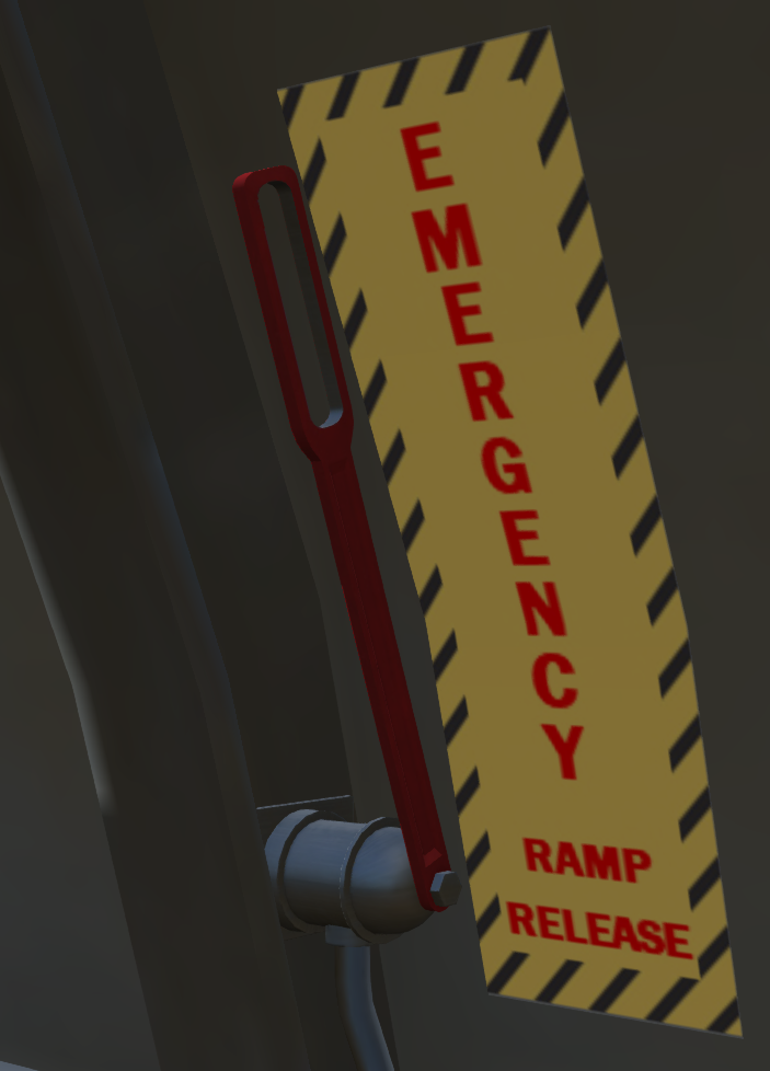
An emergency ramp release (see <xr id='fig:rampRelease'/>) is located in the rear of the aircraft on the right side near the ramp. Pulling this lever will release pressure from the hydraulic actuators and allow it to fall by gravity. Return the lever to the up position to reengage the hydraulic actuators and restore normal functioning to the ramp. | An emergency ramp release (see <xr id='fig:rampRelease'/>) is located in the rear of the aircraft on the right side near the ramp. Pulling this lever will release pressure from the hydraulic actuators and allow it to fall by gravity. Return the lever to the up position to reengage the hydraulic actuators and restore normal functioning to the ramp. | ||
| + | |||
| + | ==== Emergency Locator Transmitter ==== | ||
| + | |||
| + | The aircraft is equipped with an Emergency Locator Transmitter (ELT) in the aft cabin on the right side wall. The ELT is equipped with a G switch that when armed, will activate the ELT in the event of a crash and start broadcasting an emergency locator signal which can be detected by ground stations and suitably equipped aircraft. | ||
| + | The ELT unit has a control switch with three positions: | ||
| + | *OFF - The unit is off and will not activated | ||
| + | *ARM - The unit is armed and will activate in the event of a crash | ||
| + | *ON - Activates the unit to start transmitting the emergency locator signal, to be used for testing purposes. | ||
| + | <span style="color:#f00">NOTE: ELT testing is only to be carried out in the first 5 minutes of the hour and is limited to 3 sweeps of the signal.</span> | ||
| + | |||
| + | ==== Portable Fire Extinguisher ==== | ||
| + | A portable ABC dry chem type fire extinguisher is provided in the cockpit. This extinguisher is suitable for extinguishing small electrical fires. Click on it to use. | ||
=== APU === | === APU === | ||
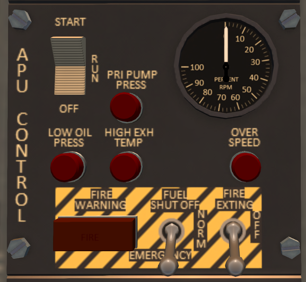
| Line 270: | Line 281: | ||
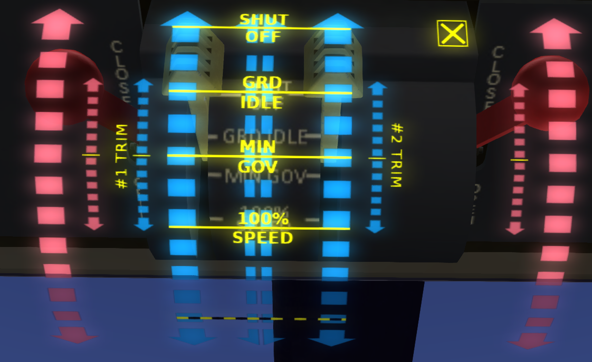
To move an emergency throttle, click on one of the red scales of the engine control overlay. The large scales move the throttle to the selected position, while the smaller scales next to it are for trim, nudging the throttle in the indicated direction. | To move an emergency throttle, click on one of the red scales of the engine control overlay. The large scales move the throttle to the selected position, while the smaller scales next to it are for trim, nudging the throttle in the indicated direction. | ||
| + | |||
| + | ==== Engine Fuel Control System ==== | ||
| + | |||
| + | Engine fuel is controlled by two Fuel Control Units, one on each engine. The fuel control units are hydro-mechanical control units that control engine speed by adjusting the fuel flow to each engine. Each fuel control unit consists of two sections, a metering section and a computing section. The metering section receives filtered fuel from the fuel filter and delivers it to the engine, adjusting the fuel flow rate according to the signals from the computing section. The computing section is a mechanical device that takes the signals for power turbine speed(N2) and engine control lever position and determines the proper fuel flow to the engine to maintain that speed and signals the metering section how much fuel to deliver to the engine. As load is applied to the engines, the engine speed will start to drop, the fuel control unit will sense this drop and apply more fuel to return engine speed to the selected value. There may be a momentary lag as the fuel control unit reacts. | ||
| + | |||
| + | <span style="color:#f00">Caution: The fuel control units are sensitive mechanical devices and must be supplied with clean fuel. Contaminated fuel may cause damage.</span> | ||
==== Ignition System ==== | ==== Ignition System ==== | ||
| Line 276: | Line 293: | ||
Ignition switches are located on the lower left side of the upper console. There is one three position rocker switch for each engine. The ignition system is powered by the DC bus. In the center OFF position, the engine igniters are deenergized. A spring-loaded TEST position for each rocker can be used to test the igniters. When held in the TEST position with DC power active, a clicking sound will be heard. The igniters should never be tested except when the engine control levers are in the SHUT OFF position, the starters are not running, and the engine fuel values are closed. In the NORM position, the igniters will activate while the starter is running. This position should be used for normal start and while engine is operating. | Ignition switches are located on the lower left side of the upper console. There is one three position rocker switch for each engine. The ignition system is powered by the DC bus. In the center OFF position, the engine igniters are deenergized. A spring-loaded TEST position for each rocker can be used to test the igniters. When held in the TEST position with DC power active, a clicking sound will be heard. The igniters should never be tested except when the engine control levers are in the SHUT OFF position, the starters are not running, and the engine fuel values are closed. In the NORM position, the igniters will activate while the starter is running. This position should be used for normal start and while engine is operating. | ||
| − | <span style="color:#f00">WARNING: Do not advance engine control levers out of SHUT OFF with the igniters active until N2 is above 20%.</span> | + | <span style="color:#f00">WARNING: Do not advance engine control levers out of SHUT OFF with the igniters active until N2 is above 20%.</span> |
==== Starter System ==== | ==== Starter System ==== | ||
| Line 298: | Line 315: | ||
The electrical field from the starter motor will cause a change in the heading indicated on the magnetic compass. For this reason, it is suggested that the crew note the magnetic compass heading before engaging the starter so that they can confirm the starter dropout occurs at 35% N1. This change in the compass is the only way to know that starter dropout has occurred. | The electrical field from the starter motor will cause a change in the heading indicated on the magnetic compass. For this reason, it is suggested that the crew note the magnetic compass heading before engaging the starter so that they can confirm the starter dropout occurs at 35% N1. This change in the compass is the only way to know that starter dropout has occurred. | ||
| + | ====Engine Chip Detectors==== | ||
| + | Each engine has a chip detector installed in the oil system. The chip detectors will activate the appropriate engine chip warning light when metal chips of sufficient size are detected in the engine oil. The presence of metal chips in the engine oil usually signals imminent failure of the engine. | ||
==== Primary Engine Instruments ==== | ==== Primary Engine Instruments ==== | ||
| Line 340: | Line 359: | ||
==== Engine Operating Limitations ==== | ==== Engine Operating Limitations ==== | ||
| − | + | Torque Limits | |
| + | *Continuous: 86% | ||
| + | *Maximum Twin Engine: 103% | ||
| + | *Maximum Single Engine: 123% | ||
| + | |||
| + | N2 Limits: | ||
| + | |||
| + | *Continuous 110% | ||
=== Fuel System === | === Fuel System === | ||
| Line 510: | Line 536: | ||
==== AFCS Chat Commands ==== | ==== AFCS Chat Commands ==== | ||
| − | + | The following chat commands can be used with the AFCS: | |
{| class=wikitable | {| class=wikitable | ||
| Line 606: | Line 632: | ||
[[File:s61-pri-hyd.png|thumb|right| | [[File:s61-pri-hyd.png|thumb|right| | ||
<figure id="fig:prihyd"><caption>Primary and Auxiliary Hydraulic Systems</caption></figure> | <figure id="fig:prihyd"><caption>Primary and Auxiliary Hydraulic Systems</caption></figure> | ||
| + | ]] | ||
| + | |||
| + | [[File:s61-hyd-switch.png|thumb|right| | ||
| + | <figure id="fig:hydswitch"><caption>Primary and Auxiliary Disable Switch</caption></figure> | ||
]] | ]] | ||
| Line 614: | Line 644: | ||
==== Flight Control Hydraulics ==== | ==== Flight Control Hydraulics ==== | ||
| − | The primary and auxiliary hydraulic systems (see <xr id='fig:prihyd'/>) provide boost power to operate the flight controls. The flight servos also limit feedback of vibration in the rotor system to the flight controls. These act in conjunction with the direct linkages from the flight controls to the swash plate to reduce the forces needed to actuate the controls. Each system operates independently and operates a similar set of servos. In normal operation, both systems are in use during flight, | + | The primary and auxiliary hydraulic systems (see <xr id='fig:prihyd'/>) provide boost power to operate the flight controls. The flight servos also limit feedback of vibration in the rotor system to the flight controls. These act in conjunction with the direct linkages from the flight controls to the swash plate to reduce the forces needed to actuate the controls. Each system operates independently and operates a similar set of servos. In normal operation, both systems are in use during flight. In the event that one of the systems fails, the affected system should be shut off with a switch on the collective (see <xr id='fig:hydswitch'/>) to relieve the excessive control forces the drag produced by the failed system. |
| + | |||
===== Primary Hydraulic System ===== | ===== Primary Hydraulic System ===== | ||
| Line 730: | Line 761: | ||
An external power port is located at the front of the aircraft on the right-hand side (see <xr id='fig:extpwr'/>). A Ground Power Unit (GPU) can be connected to this port to provide DC and AC power on the aircraft. In addition to connecting the ground power unit, the EXT PWR switch in the cockpit must also be ON in order for external power to be available in the aircraft. To recharge the battery, the BATTERY switch must also be on. When external power is connected and turned on a green EXT PWR advisory light will illuminate in the cockpit. | An external power port is located at the front of the aircraft on the right-hand side (see <xr id='fig:extpwr'/>). A Ground Power Unit (GPU) can be connected to this port to provide DC and AC power on the aircraft. In addition to connecting the ground power unit, the EXT PWR switch in the cockpit must also be ON in order for external power to be available in the aircraft. To recharge the battery, the BATTERY switch must also be on. When external power is connected and turned on a green EXT PWR advisory light will illuminate in the cockpit. | ||
| − | + | === Ramp === | |
| − | |||
| − | |||
| − | |||
| − | |||
| − | |||
| − | |||
| − | |||
| − | |||
| − | |||
| − | |||
| − | |||
| − | |||
| − | |||
| − | |||
| − | |||
| − | |||
| − | |||
| − | |||
| − | |||
| − | |||
| − | |||
| − | |||
| − | |||
| − | |||
| − | |||
| − | |||
| − | |||
| − | |||
| − | |||
| − | |||
| − | |||
| − | |||
| − | |||
| − | |||
| − | |||
| − | |||
| − | |||
[[File:s61-ramp-ctrl.png|thumb|right|50px| | [[File:s61-ramp-ctrl.png|thumb|right|50px| | ||
| Line 773: | Line 767: | ||
]] | ]] | ||
| − | The S-61R is equipped with a rear ramp consisting of two independently controllable sections, the forward ramp and the aft ramp. The forward ramp hinges directly to the floor of the helicopter, extending the main cabin floor area when the ramp is in the up position. The aft ramp shares a hing on the aft side of the forward ramp. When both ramps are in the closed position, the helicopter aft cabin is closed off by the ramp. When both ramps are in the open position, the ramp can be used for loading the helicopter. There is also an emergency release for the aft ramp that allows it to be used as an emergency exit. The ramp system operates off the utility hydraulic system. The ramp can be controlled from a panel next to the pilot on the middle console or through a panel in the aft area of the aircraft. | + | The S-61R is equipped with a rear ramp consisting of two independently controllable sections, the forward ramp and the aft ramp. The forward ramp hinges directly to the floor of the helicopter, extending the main cabin floor area when the ramp is in the up position. The aft ramp shares a hing on the aft side of the forward ramp. When both ramps are in the closed position, the helicopter aft cabin is closed off by the ramp. When both ramps are in the open position, the ramp can be used for loading the helicopter. There is also an emergency release for the aft ramp that allows it to be used as an emergency exit. The ramp system operates off the utility hydraulic system. The ramp can be controlled from a panel next to the pilot on the middle console or through a panel in the aft area of the aircraft. The Aft ramp may be opened in flight or on water, the forward ramp may only be opened on the ground. |
| − | + | ==== Pilot Ramp Control Panel ==== | |
The pilot ramp control panel (see <xr id='fig:rampctrl'/>) includes the following three switches: | The pilot ramp control panel (see <xr id='fig:rampctrl'/>) includes the following three switches: | ||
| Line 792: | Line 786: | ||
In addition to the three switches, the ramp control panel includes two indicator lights above each ramp control switch. These indicator lights will illuminate when the ramp corresponding to its switch is in motion. | In addition to the three switches, the ramp control panel includes two indicator lights above each ramp control switch. These indicator lights will illuminate when the ramp corresponding to its switch is in motion. | ||
| − | + | ==== Crew Ramp Control Panel ==== | |
[[File:s61-ramp-aftctrl.png|thumb|right|200px| | [[File:s61-ramp-aftctrl.png|thumb|right|200px| | ||
| Line 822: | Line 816: | ||
|} | |} | ||
| − | + | === Crew Access Ladder and Rescue Platform === | |
<div style="clear: both" ></div> | <div style="clear: both" ></div> | ||
| Line 844: | Line 838: | ||
==== Cockpit Lighting ==== | ==== Cockpit Lighting ==== | ||
| + | |||
| + | [[File:s61-interior-light-panel.png|thumb|right| | ||
| + | <figure id="fig:interior-lighting"><caption>Cockpit Lighting Panel</caption></figure> | ||
| + | ]] | ||
| + | |||
| + | The cockpit lights are controlled through knobs on the overhead panel. Each knob has five intensity levels at OFF, 25%, 50%, 75% and 100% intensities. These lights are described in the following table: | ||
| + | |||
| + | {| class=wikitable | ||
| + | ! Light | ||
| + | ! Power Source | ||
| + | ! Description | ||
| + | |- | ||
| + | |CO-PILOT FLT INST||AC1||''Co-pilot-side flight instrument lights''. These lights are mounted under the dash hood and provide lighting for the co-pilot-side flight instruments. | ||
| + | |- | ||
| + | |SECONDARY INST||DC||''Secondary instrument lights''. These lights are mounted overhead behind the pilot seats and illuminate the full instrument panel with red light. | ||
| + | |- | ||
| + | |LOWER||AC2||''Lower Console Lights''. These lights are mounted overhead behind the pilot seats and illuminate the lower console between the pilot and co-pilot seats. This switch controls the white lower console light. | ||
| + | |- | ||
| + | |LOWER CONSOLE RED LTS||AC2||''Lower Console Red Lights''. This light his mounted in the same housing as the LOWER light. It also illuminates the lower console but with red light. | ||
| + | |- | ||
| + | |OVHD||AC1||''Overhead console light''. This light is mounted behind the pilot seats and illuminates the overhead console with red light. | ||
| + | |- | ||
| + | |NON-FLT INST||AC1||''Non-flight instrument lights''. These lights are mounted under the dash hood and provide lighting for the non-flight instruments in the center of the main console. | ||
| + | |- | ||
| + | |PILOT FLT INST||AC2||''Pilot-side flight instrument lights''. These lights are mounted under the dash hood and provide lighting for the pilot-side flight instruments. | ||
| + | |} | ||
==== Main Cabin Lighting ==== | ==== Main Cabin Lighting ==== | ||
| + | |||
| + | {| class=wikitable | ||
| + | ! Light | ||
| + | ! Power Source | ||
| + | ! Description | ||
| + | |- | ||
| + | |EMER EXIT LTS||DC/Internal Battery||''Emergency Exit Lights''. Several emergency exit lights are mounted throughout the aircraft to provide illumination for safe egress in the event of an accident. These lights contain their own power source and do not need aircraft power to function. They are controlled through a three-position switch on the upper console labeled EMER EXIT LTS with TEST, OFF and ARM positions. In the TEST position, all emergency lights will illuminate. Use this to test if the lights are functioning and the internal batteries are charged. In the ARM position, the lights will trigger after an impact or hard landing. If the lights illuminate in the ARM position, click one of the emergency light fixtures to reset it. | ||
| + | |- | ||
| + | |CABIN LIGHTS||DC||''Main Cabin Lights''. These lights are mounted in four separate fixtures on the ceiling in the main cabin. They are controlled through a switch on the RDF operator console with RED, OFF and WHITE positions. | ||
| + | |} | ||
==== Exterior Lighting ==== | ==== Exterior Lighting ==== | ||
| Line 866: | Line 896: | ||
! Description | ! Description | ||
|- | |- | ||
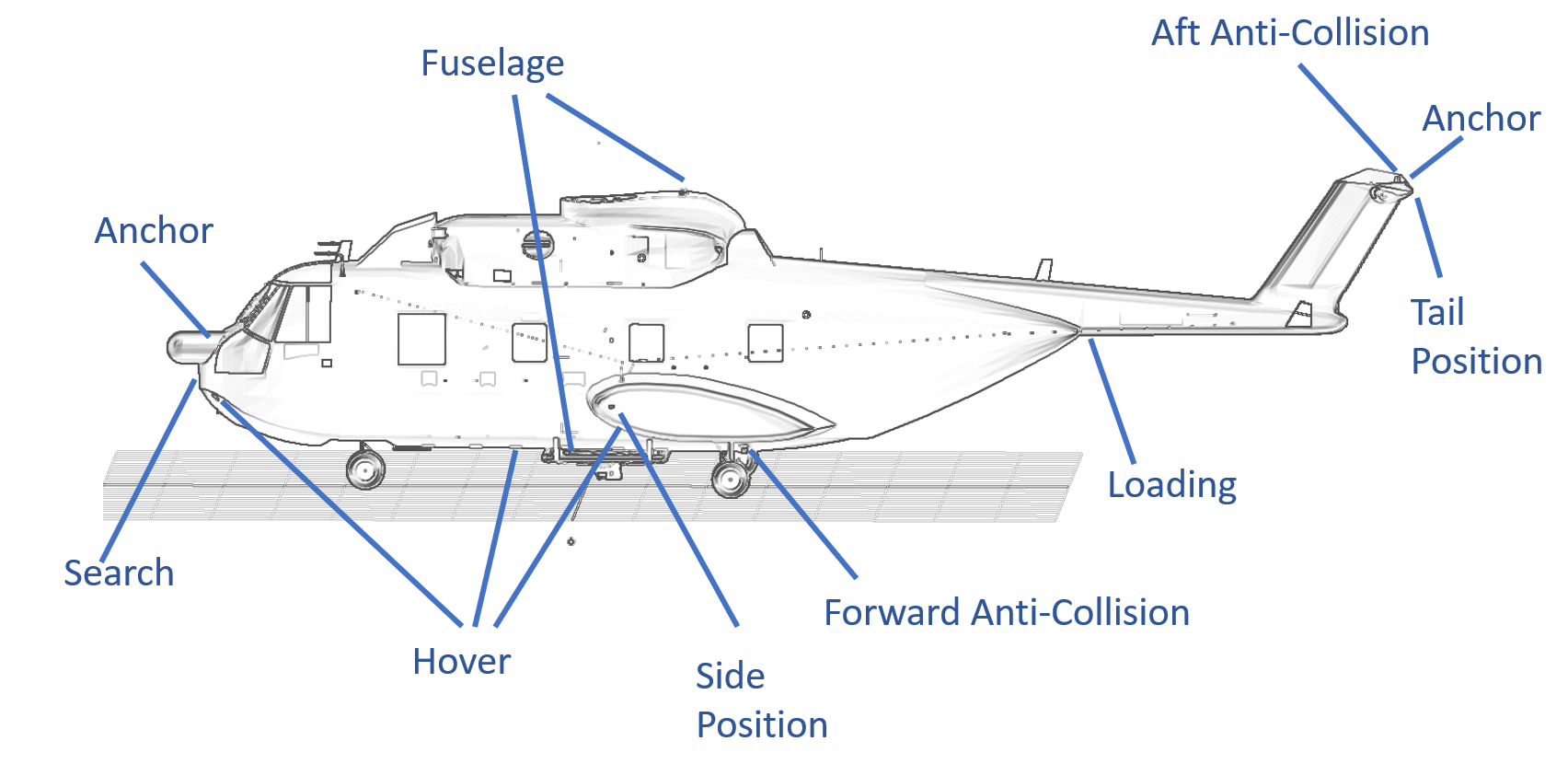
| − | | | + | |ANCHOR||Battery Hot||''Anchor Lights''. The lights should be used anytime the aircraft is anchored. These lights are designed to operate off the hot battery bus and will operate even when the main BATTERY switch is OFF. |
|- | |- | ||
| − | | | + | |FUSELAGE||DC||''Fuselage Lights''. A white fuselage is mounted on the top and bottom of aircraft. The fuselage light is used to make the aircraft more visible for night formation flying. The fuselage light is controlled by a 3-position switch with DIM, OFF and BRT (bright) positions. |
|- | |- | ||
| − | | | + | |ANTI-COLLISION||DC||''Anti-Collision Lights''. The anti-collision lights should be on any time a rotor is moving warn others of the danger, and in flight to improve aircraft visibility. There are two anti-collision lights, each controlled by a separate switch: a forward anti-collision light mounted on the underside of the aircraft, and and aft anti-collision light mounted on the top of the vertical stabilizer. The forward anti-collision light should be turned off prior water landings. |
|- | |- | ||
| − | | | + | |POSITION||DC||''Position Lights''. Position lights should be used between sunset and sunrise and during total solar eclipses. The white position is mounted on the back of the vertical stabilizer, the red position light is mounted on the left sponson, and the green position light is mounted on the right sponson. The position lights are controlled by a mode switch and a brightness switch. The mode switch has positions STEADY, OFF, and FLASH. A separate brightness switch has positions DIM and BRT (bright). When the mode switch is off, the brightness switch is ignored. |
|- | |- | ||
| − | | | + | |HOVER||DC||''Hover Lights''. Five hover lights improve visibility around the aircraft while hovering at night. Two lights are mounted under each sponson, one light on the belly, and two additional lights on the nose. The hover lights are controlled by a two-position switch. |
|- | |- | ||
| − | | | + | |LOADING||DC||''Loading Light''. Located under the tail boom behind the main ramp. This light is used to assist in loading by ramp at night. This light is controlled by an additional switch labeled LOADING below the main set of exterior light switches. This switch controls both an external loading light, and an interior loading light over the ramp on the interior of the helicopter. |
|- | |- | ||
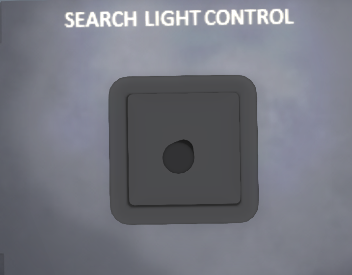
| − | | | + | |SEARCH||DC||''Search Light''. A steerable search light is mounted in the battery door. This light is controlled by a switch with STOW, OFF and ON positions. In the OFF position, the light will not illuminate, but the light gimbal will remain in its current position. In the ON position, the light will illuminate and a joystick on the center console (see <xr id='fig:search-joy'/>) can be used to aim the light. Use the chat command "j''dir'' spotLightControl" to move the spotlight through chat commands (where ''dir'' is one or more of f,b,r,l for forward, back, right, left). Each chat command will move the control in that direction for a brief time, then return it to center. |
|} | |} | ||
| − | === | + | === Caution - Advisory Panel === |
[[File:s61-warning-panel.png|thumb|right| | [[File:s61-warning-panel.png|thumb|right| | ||
| − | <figure id="fig:warning-panel"><caption> | + | <figure id="fig:warning-panel"><caption>Caution - Advisory Panel</caption></figure> |
]] | ]] | ||
| + | |||
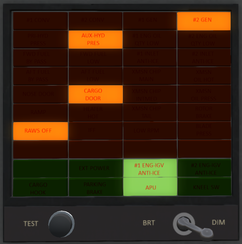
| + | The Caution - Advisory Panel (see <xr id='fig:warning-panel' />) is located in the center of the main panel and contains an array of indicator lights indicating potential malfunctions or alert conditions in the helicopter. A complete list of all the lights and their meanings are shown in [[S-61R Pelican/Appendices|Appendices]]. A switch on the bottom with DIM and BRT setting can select the brightness of the lights. There is also a push button in the lower left corner that can be used to test the alert lights. | ||
| + | |||
| + | In addition to the main bank of lights, there is an additional MASTER CAUTION and FIRE light mounted on the edge of dash hood. The MASTER CAUTION light will illuminate when any of the caution lights illuminate. You can touch the MASTER CAUTION light to make it go out until any new alerts are posted. The FIRE light will go on when any engine or APU fire warning lights is triggered. | ||
Latest revision as of 16:35, 28 June 2022
SECTION 2. SYSTEMS
Contents
- 1 Helicopter
- 2 Emergency Equipment
- 3 APU
- 4 Engines and Related Systems
- 5 Fuel System
- 6 Flight Controls and AFCS
- 7 Hydraulic Systems
- 8 Power Train System
- 9 Rotor System
- 10 Electrical System
- 11 Ramp
- 12 Crew Access Ladder and Rescue Platform
- 13 Lighting
- 14 Caution - Advisory Panel
1 Helicopter
1.1 General
The Shergood S-61R is a twin-turbine engine helicopter designed for transportation of cargo and for search-and-rescue operations in day, night, visual and instrument conditions. The helicopter is powered by two 1,400 shp General Electric T58-GE-10 turbo-shaft engines mounted above the main cabin in front of the main transmission. Drive shafts from each engine is connected to the main transmission through a mixing unit such that the rotors will continue to spin even if one engine fails. When the rotors are not turning, an APU (Auxiliary Power Unit) can be used to supply electrical power and hydraulic pressure. Fuel is carried in compartments in the lower hull of the helicopter with forward and aft auxiliary and main tanks. An entrance door is located on the forward right side of the main cabin, while a hydraulically powered ramp is in the back. The helicopter is fully amphibious with a "flying boat" style design.
1.2 Gross Weight
The maximum gross weight is 22,050 pounds.
1.3 Pilot-Side Instrument Panel
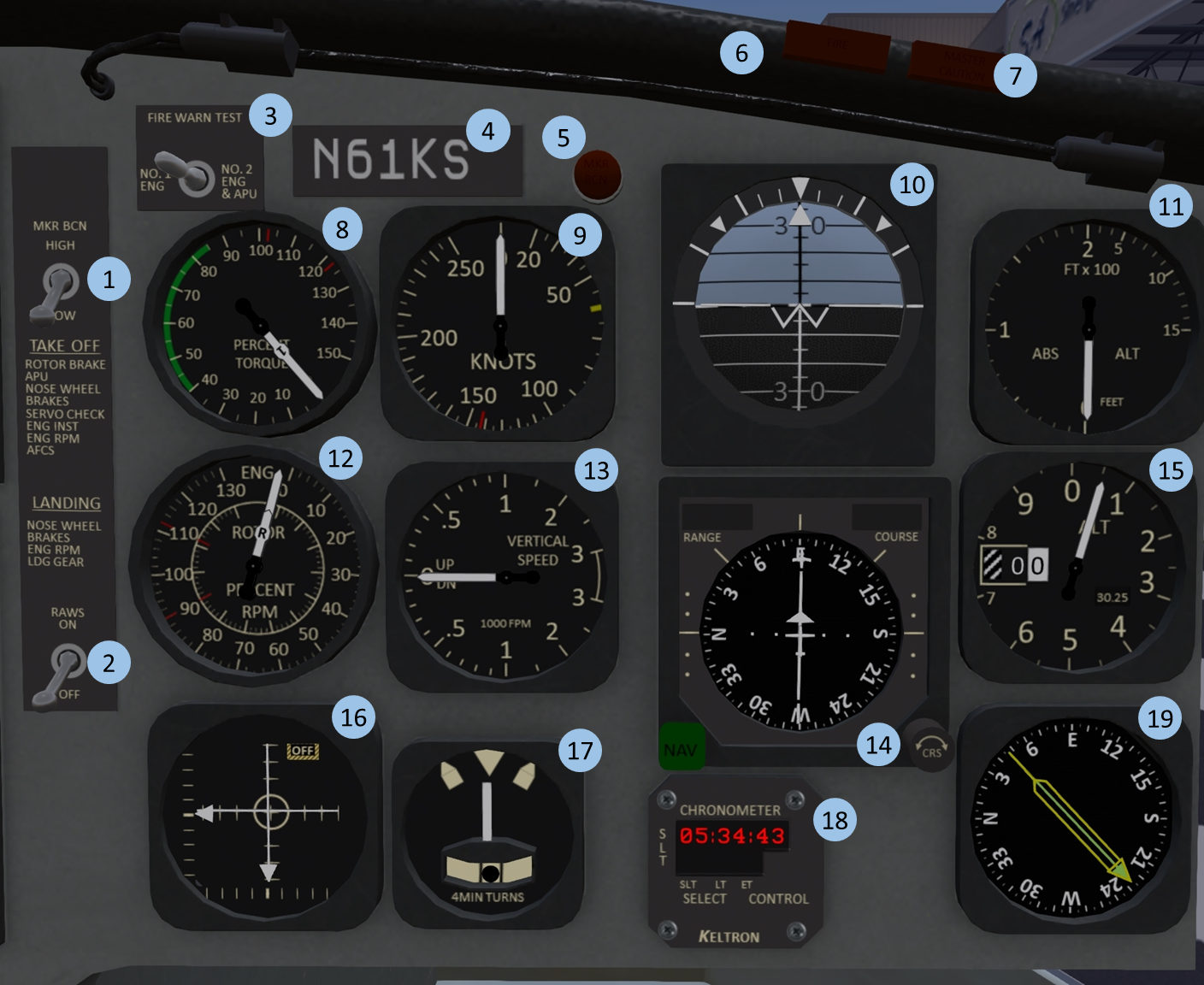
| 1. Marker Beacon Intensity | 2. RAWS Warning | 3. Fire Warning Test | 4. Tail-Number plate |
| 5. Marker Beacon Light | 6. Fire Warning Light | 7. Master Warning Light | 8. Torque Indicator |
| 9. Airspeed Indicator | 10. Attitude Indicator | 11. Radar Altimeter | 12. Tri-Needle RPM |
| 13. Vertical Speed Indicator | 14. HSI | 15. Altimeter | 16. AFCS Indicator |
| 17. Turn/Slip Indicator | 18. Clock | 19. Radio-Magnetic Indicator |
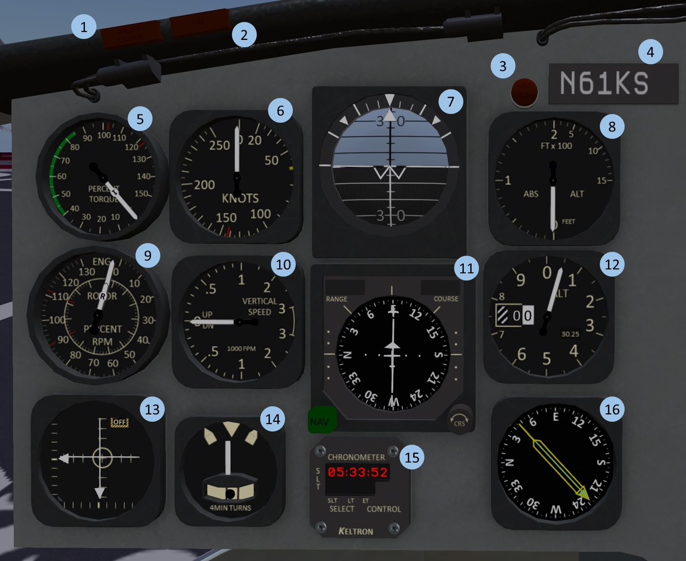
1.4 Co-Pilot-Side Instrument Panel
| 1. Master Caution Light | 2. Fire Warning Light | 3. Marker Beacon Light | 4. Tail-Number plate |
| 5. Torque Indicator | 6. Airspeed Indicator | 7. Attitude Indicator | 8. Radar Altimeter |
| 9. Tri-Needle RPM | 10. Vertical Speed Indicator | 11. HSI | 12. Altimeter |
| 13. AFCS Indicator | 14. Turn/Slip Indicator | 15. Clock | 16. Radio-Magnetic Indicator |
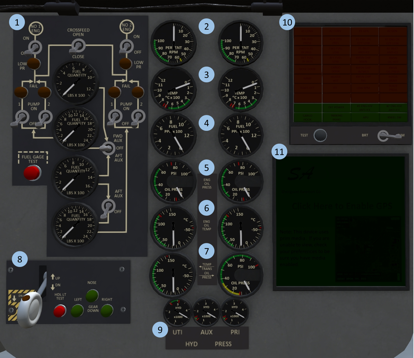
1.5 Center Instrument Panel
| 1. Fuel Panel | 2. N1 Gauge | 3. Turbine Inlet Temp (TIT) | 4. Fuel Flow |
| 5. Oil Pressure | 6. Oil Temp. | 7. Trans. Temp & Press. | 8. Gear Panel |
| 9. Hydraulic Pressure | 10. Warning/Alert Panel | 11. GPS Moving Map |
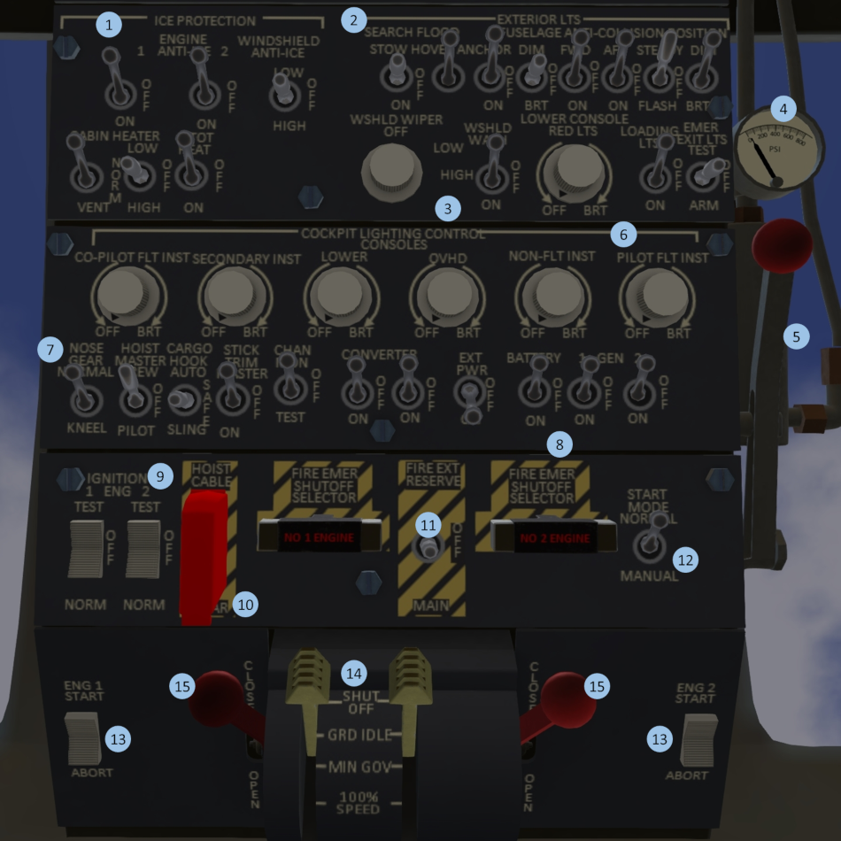
1.6 Overhead Panel
| 1. Ice Protection | 2. Exterior Lighting | 3. Windshield Wiper/Wash | 4. Rotor Brake Press. |
| 5. Rotor Brake | 6. Interior Lighting | 7. System Master Switches | 8. Electrical Systems |
| 9. Ignition | 10. Hoist Cable Shear | 11. Fire Protection | 12. Start Mode |
| 13. Starter | 14. Engine Control | 15. Emergency Throttles |
1.7 Middle Panel
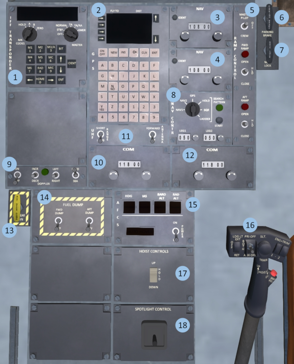
| 1. IFF Trasponder | 2. GPS Panel | 3. #1 NAV Radio | 4. #2 NAV Radio |
| 5. Rear Ramp Control | 6. Parking Brake | 7. Nosewheel Lock | 8. Navigation Control |
| 9. Doppler Panel | 10. Antenna Control | 11. #1 COM Radio | 12. #2 COM Radio |
| 13. Emergency Gear Down | 14. Fuel Dump Panel | 15. AFCS | 16. Hydraulic System Select |
| 17. Hoist Control | 18. Spotlight Control |
1.8 Landing Gear Systems
The S61 has a tricycle type landing gear system with a nosewheel in front and two main gear in sponsons in the back. The gear is hydraulically actuated through the utility hydraulic system. The system includes a squat switch to prevent accidentally raising the gear while the helicopter is on the ground.
1.8.1 Landing Gear Panel
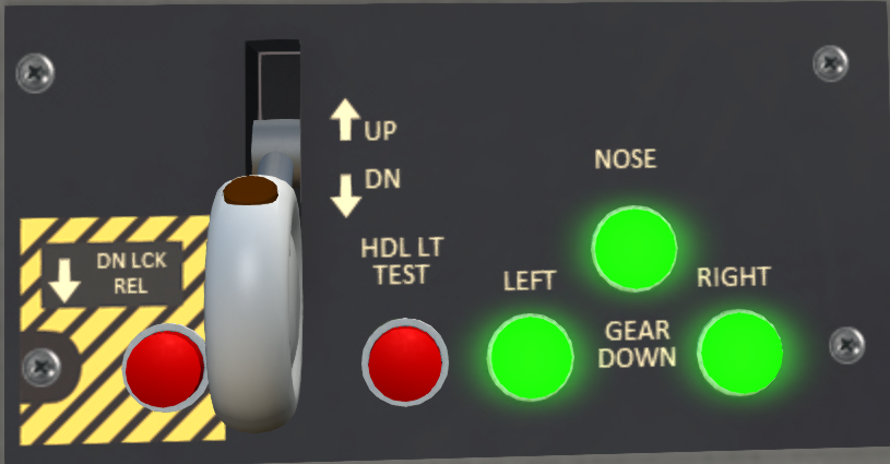
The landing gear panel (see Figure 6) is located on the center portion of the main console. Three lights on the right-hand side of the panel illuminate green when the respective gear is down and locked. The gear is controlled by a two position lever with a red "in motion" indicator light. The light illuminate when the landing gear are in motion. A test button labeled "HLD LT TEST" can be pressed to test the "in motion" indicator light. Finally, a DN LCK REL button can be used to override the squat switch allowing gear to be raised while on the ground.
1.8.2 Landing Gear Malfunctions
Normal wear and tear, or damage through a hard landing can cause the landing gear to malfunction. Malfunctions may affect retracting, lowering or both. When changing the gear position always verify the red "in-motion" light on the handle comes on, then goes out several seconds later. When lowering gear, always verify you get three green lights indicating the gear is down and locked.
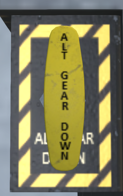
In the event that the gear fails to retract, travel to the next point of landing can be continued, but caution should be used to keep the landing as soft as possible. In the event that gear fails to lower, there is an emergency gear handle (see Figure 7) on the copilot side of the middle console. This handle deploys a compressed air bottle to force the gear into the down position. After use, the air bottle must be replaced before it can be used again. Once the emergency gear extension system is activated, the gear is prevented from retracting until repairs are made to the gear system.
1.8.3 Kneel System
A nose gear kneel switch (see Figure 8) is located on the upper console. This switch is only effective when the landing gear handle is in the down position. Flipping this switch will cause the nose wheel to retract to a 50% retracted position. This can be used to increase the clearance under the tail for loading the helicopter through the ramp. Like the landing gear system, the kneel system requires utility hydraulic pressure to operate.
1.9 Parking Brake
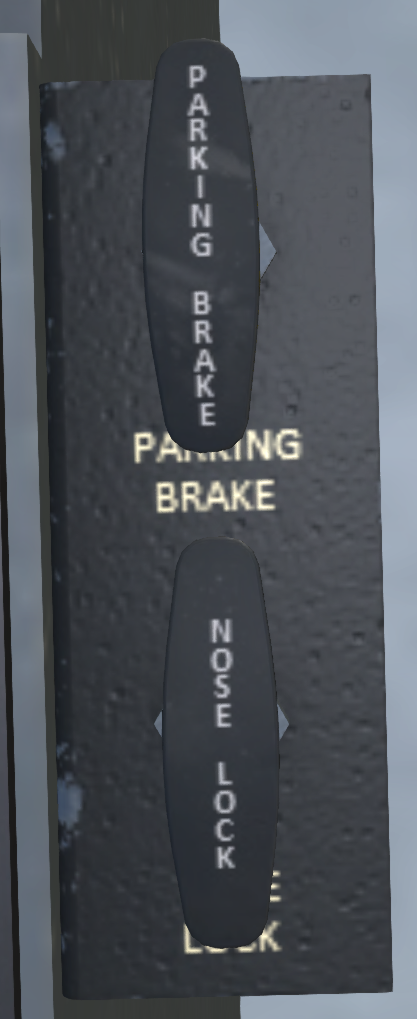
A parking brake (see Figure 9) is located on the pilot side of the middle console. Activating the parking brake will increase resistance to ground movement. Click the handle to toggle its position, or use the chat command:
s brake
to toggle it.
1.10 Nose Wheel Lock
A nosewheel lock (see Figure 9) is located on the pilot side of the middle console just below the parking brake. Activating the parking brake will increase resistance to rotation while on the ground. Click the handle to toggle its position, or use the chat command:
s noselock
to toggle it. The nosewheel lock should be used during rotor engagement to prevent the helicopter from turning on the ground during the high-torque stages of engagement.
2 Emergency Equipment
2.1 Engine Fire Detection System
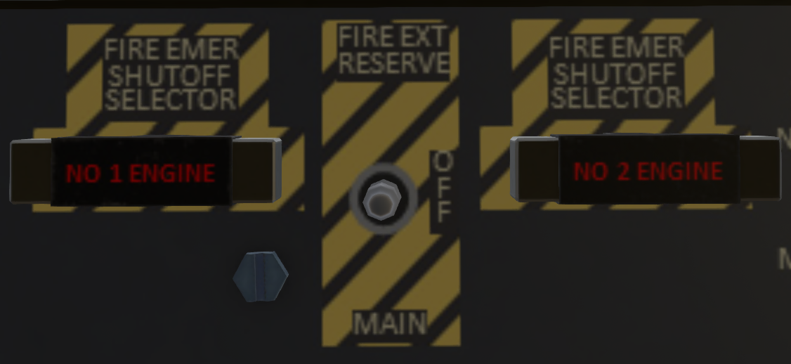
The S61 is equipped with fire sensors and two fire extinguisher bottles to detect and mitigate engine fires. The fire detection system for the #1 and #2 engines is power by the #1 and #2 AC bus, respectively. The fire detection panel is located on the upper console behind the throttle quadrant (see Figure 10). The panel has two fuel cut-off handles for each engine. The handles will light up when a fire is detected (if AC power is available). Pulling a handle will cut off fuel to an engine through a mechanical linkage.
The fire extinguishers are activate by a 3-position toggle switch between the fuel cut-off handles. The switch will have no effect except when a handle is pulled. This switch should normally be left in the middle OFF position. When deploying an extinguisher, first pull the cut-off handle for the affected engine, then switch the FIRE EXT switch to MAIN. This will deploy the bottle corresponding to the affected engine (#1 bottle for #1 engine, #2 bottle for #2 engine). If a single bottle is insufficient to extinguish a fire, you can switch the FIRE EXT switch to the RESERVE position. This will deploy the bottle from the opposite engine (#2 bottle for #1 engine, or #1 bottle for #2 engine). The fire extinguisher bottles are single use. Once they have been used, they must be replaced on the ground.
2.2 APU Fire Detection System
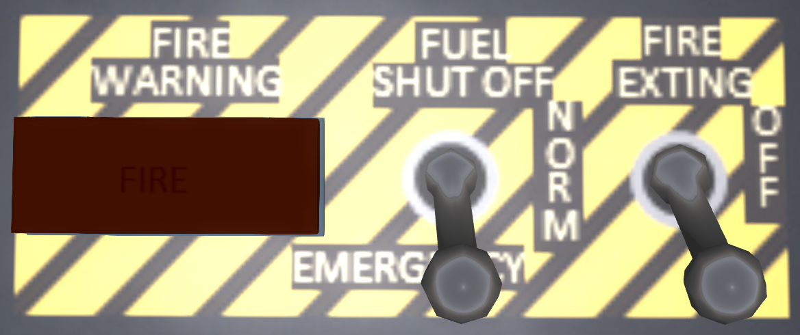
The APU fire detection panel (see Figure 11) is on the APU panel located on the pilot's side panel. The APU fire detection and mitigation system operates off the DC bus. A warning light will illuminate to indicate a fire has been detected. To activate the fire suppression system, flip the FUEL SHUT OFF switch and FIRE EXTING switches to the forward position.
2.3 Fire Warning Test Panel
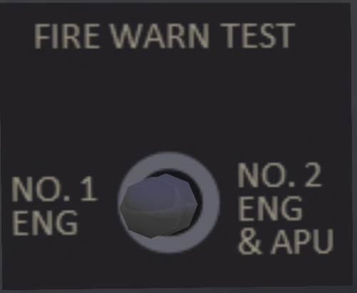
A fire warning test panel is located on the pilot side of the main panel (see Figure 12). The panel contains a three-position switch. Flipping the switch to either side from the center position will test the fire detection system and lights for the indicated systems. When the switch is moved to the left marked NO 1 ENG, the fire detection warning light in the Engine #1 fuel cut-off handle will illuminate. When the switch is moved to the right marked NO 2 ENG & APU, the fire detection warning light in the Engine #2 fuel cut-off handle will illuminate, as well as the warning light for the APU.
2.4 Emergency Lights
Emergency lights (see Figure 13) are installed at various positions in the helicopter and provide lights for emergency evacuation in the event of a crash. They are controlled by a three position switch labeled EMER EXIT LIGHTS on the pilot-side of the upper console. In the TEST position, all emergency lights will turn on for testing. In the OFF position, the lights will always remain OFF. In the ARM position (recommended for normal flight), the emergency lights will come on in the event of a sudden acceleration or shock. Once the shock sensor has been tripped, it must be manually reset by clicking on one of the emergency lights in the helicopter.
2.5 Emergency Ramp Release
An emergency ramp release (see Figure 14) is located in the rear of the aircraft on the right side near the ramp. Pulling this lever will release pressure from the hydraulic actuators and allow it to fall by gravity. Return the lever to the up position to reengage the hydraulic actuators and restore normal functioning to the ramp.
2.6 Emergency Locator Transmitter
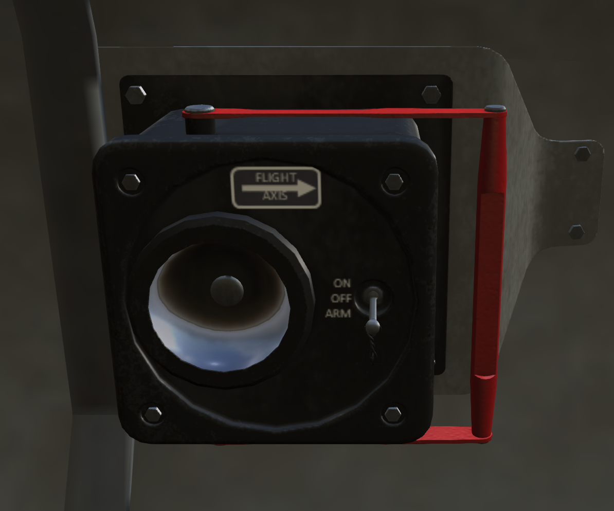
The aircraft is equipped with an Emergency Locator Transmitter (ELT) in the aft cabin on the right side wall. The ELT is equipped with a G switch that when armed, will activate the ELT in the event of a crash and start broadcasting an emergency locator signal which can be detected by ground stations and suitably equipped aircraft. The ELT unit has a control switch with three positions:
- OFF - The unit is off and will not activated
- ARM - The unit is armed and will activate in the event of a crash
- ON - Activates the unit to start transmitting the emergency locator signal, to be used for testing purposes.
NOTE: ELT testing is only to be carried out in the first 5 minutes of the hour and is limited to 3 sweeps of the signal.
2.7 Portable Fire Extinguisher
A portable ABC dry chem type fire extinguisher is provided in the cockpit. This extinguisher is suitable for extinguishing small electrical fires. Click on it to use.
3 APU
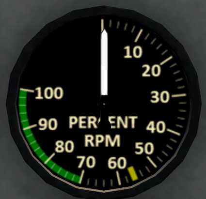
An APU is mounted aft of the main gearbox on the left-hand side of the aircraft. The APU is operated through the APU panel (see Figure 15) located on the pilot's right-side panel. The panel contains a start/mode switch, several warning lights, a tachometer, and a fire suppression sub-panel. The APU can drive the main rotor accessory section to provide hydraulic and AC power without an engine operating. A clutch disengages the APU from the transmission accessory section when the rotor RPM reaches 100%.
3.1 Starting and Stopping the APU
To start the APU, use the following sequence:
- Turn on the battery.
- Advance the rocker switch to the RUN position. The LOW OIL PRESS and HIGH EXH TEMP lights will illuminate.
- Press and hold the rocker in the START position until the RPM gauge reads at least 40%. The LOW OIL PRESS and HIGH EXH TEMP lights will go out as the APU RPM exceeds 20%.
- The RPM will continue to increase automatically. Between 70% and 78%, the rate of increase will slow while the APU clutch engages.
To stop the APU, simply move the rocker switch to the OFF position.
3.2 APU Accumulator
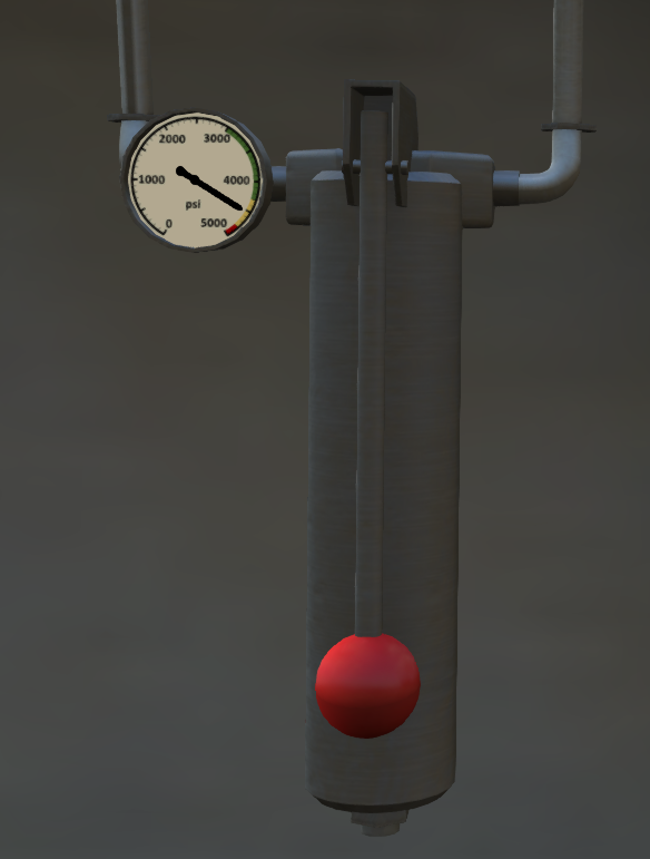
While electrical power is needed for the APU controller during startup, a hydraulic accumulator is used to actually spin up the APU turbine during start. The accumulator is mounted behind the main transmission on the right-hand side of the aircraft. An APU accumulator hand pump is mounted in the main cabin on the right-side wall behind the troop seats. If the accumulator pressure reads below 3000 psi, then the pump should be actuated by hand to recharge the accumulator. In normal operation, the accumulator will be recharged automatically from the utility hydraulic system. However, if the utility hydraulic system has failed, or the APU start sequence is started but aborted before completing the start, the accumulator pressure may fall too low to start the APU. APU starts at extremely low outside air temperatures may require higher accumulator pressures for successful start.
3.3 Warning Lights
| Light | Description |
|---|---|
| PRI PUMP PRESS | Indicates lack of fuel pressure from the priming pump. Could indicate damage to the APU. |
| LOW OIL PRESS | APU oil pressure is too low. |
| HIGH EXH TEMP | APU exhaust temperature is too high. |
| OVERSPEED | APU speed is too high. Could indicate failure of the clutch to disengage when main rotors spin up to 100%. |
| FIRE | Indicates a fire detected in the APU. |
3.4 APU Fire Detection and Suppression System
The bottom portion of the APU control panel is the APU fire detection and suppression system. A "FIRE" warning indicator on the panel will illuminate when an APU fire has been detected. The emergency fuel cut-off switch will cut off fuel to the APU through a solenoid value. A switch labeled FIRE EXTING will deploy the APU fire extinguisher. The APU fire extinguisher is separate from the extinguishers for the main engine. Once deployed, the fire extinguisher bottle must be replaced before the system can be used again.
4 Engines and Related Systems
4.1 General
The S61-R is powered by two General Electric T58-GE-10 turboshaft engines delivering 1,400 shp each. The engines are mounted above the main cabin in front of the main transmission.
4.2 Engine Control Levers
Engine control levers and emergency throttles are located on the forward overhead panel between the pilot and copilot seats. In normal operation, only the yellow engine control levers are used. To operate the levers, click in the general area of the lever to bring up the control overlay (see Figure 17). Once the overlay is active, clicking on one of the scales will move the lever under it to the selected position. To dismiss the control overlay, you can click the "X".
The blue scales in the center part of the overlay are used for the engine control levers. Clicking on one of the one of the wide blue scales will move the lever under it to the selected position. There are stops at "SHUT OFF", "GRD IDLE" (ground idle) and "MIN GOV" (minimum governed) positions. Above "MIN GOV", the engine control lever is analog and can be placed at any position to operate the engine at a specific RPM. A "100% SPEED" marking shows the approximate position for 100% RPM. In normal operations, RPM should be between 90% and 110%.
Next to each engine scale is a narrower "trim" scale. Clicking on the trim scale will nudge the engine control in the indicated direction relative to the center point. The further you click from the center point of the scale, the larger the nudge will be.
Between the two throttles is a paired scale. Clicking on this scale will move both engine control levers to the indicated position.
The engine control levers do not directly control the throttles on the engine. Instead they command a fuel controller to maintain a specific RPM. As the load on the engine is increased, the throttle is opened to maintain that RPM.
4.3 Emergency Throttle Levers
On the outside of the engine control quadrant are two emergency throttle levers. In normal operation, they are left in the CLOSED position. In the event of a fuel controller failure, the throttle will "stick" in its position when the controller failed. The emergency throttle levers have a mechanical linkage that allows them to open the throttle beyond the point where it failed, but the throttle cannot be closed through use of the emergency throttles. In practice, the first part of travel of the emergency control lever will have no effect until it is opened beyond the point of the stuck position.
When using an emergency throttle in flight, care should be taken to make collective movements as slow and gradual as possible to avoid overspeeding the engine. Adjustments to the collective or an emergency throttle should always be done while monitoring engine and rotor rpm.
To move an emergency throttle, click on one of the red scales of the engine control overlay. The large scales move the throttle to the selected position, while the smaller scales next to it are for trim, nudging the throttle in the indicated direction.
4.4 Engine Fuel Control System
Engine fuel is controlled by two Fuel Control Units, one on each engine. The fuel control units are hydro-mechanical control units that control engine speed by adjusting the fuel flow to each engine. Each fuel control unit consists of two sections, a metering section and a computing section. The metering section receives filtered fuel from the fuel filter and delivers it to the engine, adjusting the fuel flow rate according to the signals from the computing section. The computing section is a mechanical device that takes the signals for power turbine speed(N2) and engine control lever position and determines the proper fuel flow to the engine to maintain that speed and signals the metering section how much fuel to deliver to the engine. As load is applied to the engines, the engine speed will start to drop, the fuel control unit will sense this drop and apply more fuel to return engine speed to the selected value. There may be a momentary lag as the fuel control unit reacts.
Caution: The fuel control units are sensitive mechanical devices and must be supplied with clean fuel. Contaminated fuel may cause damage.
4.5 Ignition System
Ignition switches are located on the lower left side of the upper console. There is one three position rocker switch for each engine. The ignition system is powered by the DC bus. In the center OFF position, the engine igniters are deenergized. A spring-loaded TEST position for each rocker can be used to test the igniters. When held in the TEST position with DC power active, a clicking sound will be heard. The igniters should never be tested except when the engine control levers are in the SHUT OFF position, the starters are not running, and the engine fuel values are closed. In the NORM position, the igniters will activate while the starter is running. This position should be used for normal start and while engine is operating.
WARNING: Do not advance engine control levers out of SHUT OFF with the igniters active until N2 is above 20%.
4.6 Starter System
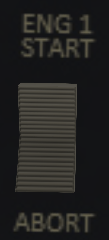
Each engine is equipped with an electric starter powered by the DC Bus. The starter is activated by a three-position rocker switch on the upper console, one for each engine (see Figure 19). To engage the starter, momentarily move the switch to the START position. The switch is spring loaded an will return to the center position, but the starter will continue to run. The starter will turn the compressor stage (N1) of the engine up to 26% to allow normal flow of fuel and air for an engine start. Pressing the ABORT side of the starter switch will disengage the starter motor.
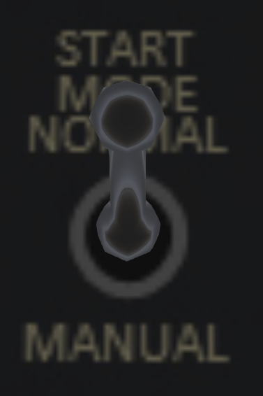
When the start mode switch (see Figure 20) is in the NORMAL position, the starter will automatically dropout when N1 exceeds 35% as the engine spins up during start. Placing the start mode switch in the MANUAL position will disable this behavior.
The electrical field from the starter motor will cause a change in the heading indicated on the magnetic compass. For this reason, it is suggested that the crew note the magnetic compass heading before engaging the starter so that they can confirm the starter dropout occurs at 35% N1. This change in the compass is the only way to know that starter dropout has occurred.
4.7 Engine Chip Detectors
Each engine has a chip detector installed in the oil system. The chip detectors will activate the appropriate engine chip warning light when metal chips of sufficient size are detected in the engine oil. The presence of metal chips in the engine oil usually signals imminent failure of the engine.
4.8 Primary Engine Instruments
4.9 Secondary Engine Instruments
4.10 Engine Warnings/Alerts
The warning/alert panel includes alert lights #1 ENG OIL QTY LOW and #2 ENG OIL QTY LOW that indicate when the oil level in the engine is low. Upon seeing this alert, flight can be continued to the next planned destination, but oil should be added to the system before continued flight.
4.11 Engine Operating Limitations
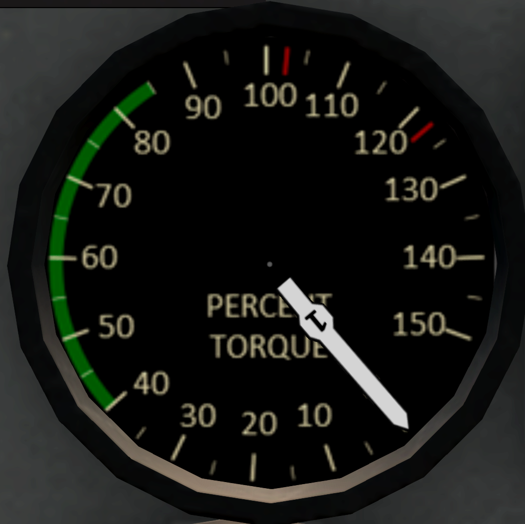
Torque Limits
- Continuous: 86%
- Maximum Twin Engine: 103%
- Maximum Single Engine: 123%
N2 Limits:
- Continuous 110%
5 Fuel System
5.1 Fuel System Overview
The S61R has two independent pressure-type fuel systems (see Figure 21) joined with a crossfeed connection. Each system (forward and aft) consists of a main tank and an auxiliary tank (four total tanks). The forward system feeds the #1 engine, while the aft system feeds the #2 engine. Boost pumps and transfer valves can be used to transfer fuel from the auxiliary to the main tanks. Each system has two boost pumps submerged in the main tank, and a third unboosted feed line. The engines also contain their own engine-driven fuel pump which can draw fuel on its own from the main tanks. An electrically operated crossfeed valve can be opened to allow crossfeed of fuel from one system to the opposite engine.
5.2 Fuel Tanks
The S61R is equipped is equipped with the following four fuel tanks having the following capacities:
| Tank | Capacity | Feeds |
|---|---|---|
| Forward Tank | 348 gal. | Feeds #1 engine |
| Aft Tank | 345 gal. | Feeds #2 engine |
| Forward Aux Tank | 184 gal. | Feeds Forward and Aft tanks |
| Aft Aux Tank | 245 gal. | Feeds Aft Tank |
Each fuel tank can be refueled using either a gravity filler or through the pressure refueling system.
5.3 Fuel Type
The S61R is designed to operate on JP-5 or JET-A fuel. When refueling with KellyFuel 3.0 or later, care must be taken to use the correct fuel type. If the incorrect fuel type is used, the fuel in that tank will be tainted, and operating the engine with tainted fuel will cause engine damage. If a tank is accidentally filled with the wrong type of fuel, the tank must be completely emptied to flush it of all contaminant. The tanks can be flushed either using the fuel dump system, or through the @Cheat menus.
5.4 Fuel Booster Pumps
Two fuel booster pumps are located in each main tank. The booster pumps are located in a collector can located in each tank. As fuel is pumped to the main engine, it is also pumped back to the main tank through an ejector unit to ensure the collector can remains full. Ejector units in the auxiliary tanks, which are activated by opening an electrically controlled valve, allow the boost pumps to transfer fuel to the main tanks.
The pumps for each tank use a different power source. In the forward system, the No 1 boost pump is powered by the #1 AC bus, and the No 2 boost pump is powered by the #1 AC Monitor Bus. In the aft system, the No 1 boost pump is powered by the #2 AC bus, and the No 2 boost pump is powered by the #2 AC Monitor Bus.
The pumps are controlled by switches on the fuel system control panel. Each pump has a low pressure indicating light above it. The indicator light is active only then the pump switch is turned on. When turning on a pump, the indicator light should flicker briefly, then go out. If the low pressure warning light remains on, it indicates the pump has failed, or is not receiving AC power from the appropriate system.
Engine may be operated with one, both or no boost pumps. However, boost pumps must be used in the following conditions:
- Above 6000 feet MSL.
- While dumping fuel
- Above 43 degrees C
- While transferring fuel
- When below 600 pounds of fuel per tank.
- Whenever a fuel filter by-pass light is illuminated
- One pump per tank during takeoff and landing
- During crossfeed operations
Note: Continuous operation of at least one boost pump per engine is recommended to prevent inadvertent operation of the aircraft during one of the above conditions.
5.5 Fuel System Control Panel
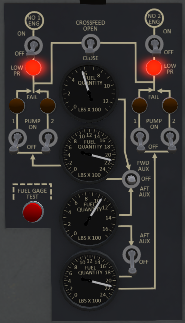
The fuel system is controlled through a fuel management panel (see Figure 22) mounted in the center portion of the main control panel.
5.5.1 Fuel Gauges
Fuel gauges for each tank are located on the center of the fuel management panel. From top to bottom the gauges are for the forward auxiliary, forward main, aft auxiliary and aft main tanks. The forward main, and aft auxiliary tank fuel gauges are powered by the #1 AC Bus, while the aft main and forward auxiliary gauges are powered by the #2 AC Bus.
5.5.2 Fuel Gauge Test Button
A red fuel gauge test button is located in the lower left corner of the fuel management panel. Press and hold this button cause all four gauges to go to a zero reading. Releasing the button will cause the gauges to return to the actual reading if they are powered and functioning correctly.
5.5.3 Fuel Shutoff Switches
At the top of the panel are two fuel shutoff valves. The shutoff switches are located below the NO 1 ENG and NO 2 ENG labels and operate electrically controlled shutoff valves.
5.5.4 Low pressure warning lights
Below the shutoff switches are two low pressure lights. The lights will illuminate when there is inadequate fuel pressure to their respective systems.
5.5.5 Boost Pump Switches
A pair of boost pump switches along with their associated low-pressure warning lights are located on each side of the fuel tank gauges. The switches on the left side are for the forward system, while the switches on the right side are for the aft system.
5.5.6 Fuel Transfer Switches
Two fuel transfer switches are located to the right of the fuel gauges. The transfer switches operate an electrically controlled valve that allows the boost pump for the tank to which fuel is flowing to force fuel from the selected auxiliary tank into that main tank. The top fuel transfer switch is three-position and can be set to transfer fuel from either the forward auxiliary to the forward main tank. The lower fuel transfer switch can be set to transfer fuel from the aft auxiliary tank to the aft main tank.
5.5.7 Crossfeed Switch
In the top center of the fuel management panel is the crossfeed switch. This switch controls an electrically controlled crossfeed valve. This switch can be used to feed an engine from the opposite fuel system. The boost pumps from the system feeding the opposite engine must be on when conducting crossfeed operations.
5.6 Low Fuel Caution Lights
The low fuel caution lights FWD FUEL LOW and AFT FUEL LOW are located on the caution and advisory panel on the main control panel. These lights will illuminate when 170-280 pounds remain in the respective main tanks. The caution lights operate off DC power. When a light illuminates, it is recommended that the pilot land as soon as practicable to refuel, or that fuel be transferred from the auxiliary tanks. Prolonged operation with a blocked filter is not recommended as it will allow unfiltered fuel to flow through the fuel control and engine, leading to possible damage to those components.
5.7 Fuel Filters
Each fuel system includes a fuel filter before the fuel is passed to the engine. The fuel filters filter contaminants from the fuel before passing into the engine. Each fuel filter includes a spring-loaded bypass valve. When the filters reach a certain level of blockage from contaminants, back-pressure from the filters will cause the valves to open, and fuel to flow around the filters.
5.7.1 Fuel Filter By-Pass Caution Lights
The fuel-filter by pass caution lights marked FWD FUEL BY-PASS and AFT FUEL BY-PASS are located on the caution and advisory panel on the main control panel. The caution lights illuminate when the fuel filter by-pass value in the respective system is open and fuel is by-passing the fuel filter. This light indicates blockage in the fuel filter and that the filter should be replaced.
5.8 Gravity Refueling
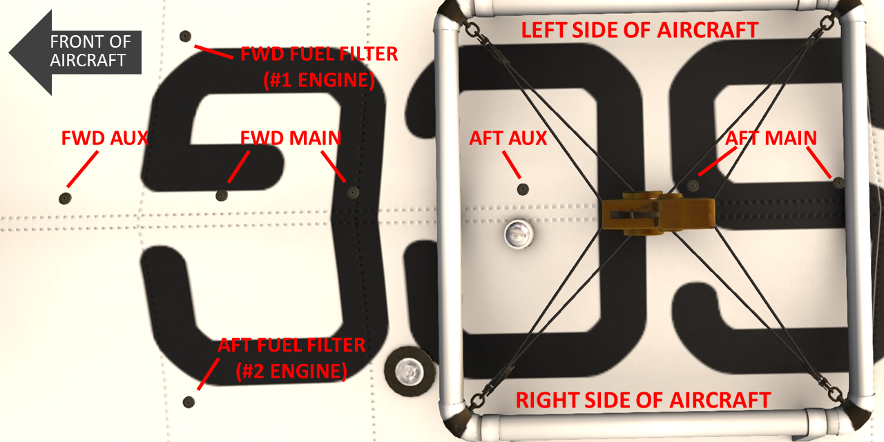
Gravity refueling ports are located on the left side of the aircraft in front of the left sponson. The forward auxiliary and tank fillers are located behind separate panel doors, while the aft auxiliary and main tank fillers are located behind a shared panel door. To refuel a tank through the gravity refuel system, the panel door must be open and the tank cap must be removed by clicking on them. Tanks can be filled using either KellyFuel or by using the "refuel" chat command.
The front strut can be used as a ground point while refueling. Always properly ground your aircraft before fueling to avoid a static discharge from sparking a potential fuel fire.
5.9 Pressure Refueling
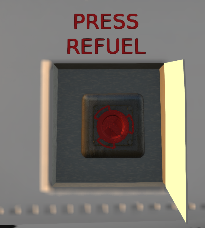
The pressure refueling port behind a panel door on the right side of the aircraft below the main cabin door. Open the panel door and undo the cap on the fuel port to prepare for fueling. Pressure refueling can be used to more rapidly refuel all tanks of the aircraft at once. Fuel flow rate while pressure refueling is approximately 10 times the rate as with gravity refueling. The pressure refueling system is compatible with KellyFuel. You can also use the "refuel" chat command while a cap is open.
The front strut can be used as a ground point while using the pressure refueling system. Always properly ground your aircraft before fueling to avoid a static discharge from sparking a potential fuel fire.
5.10 Fuel Dumping
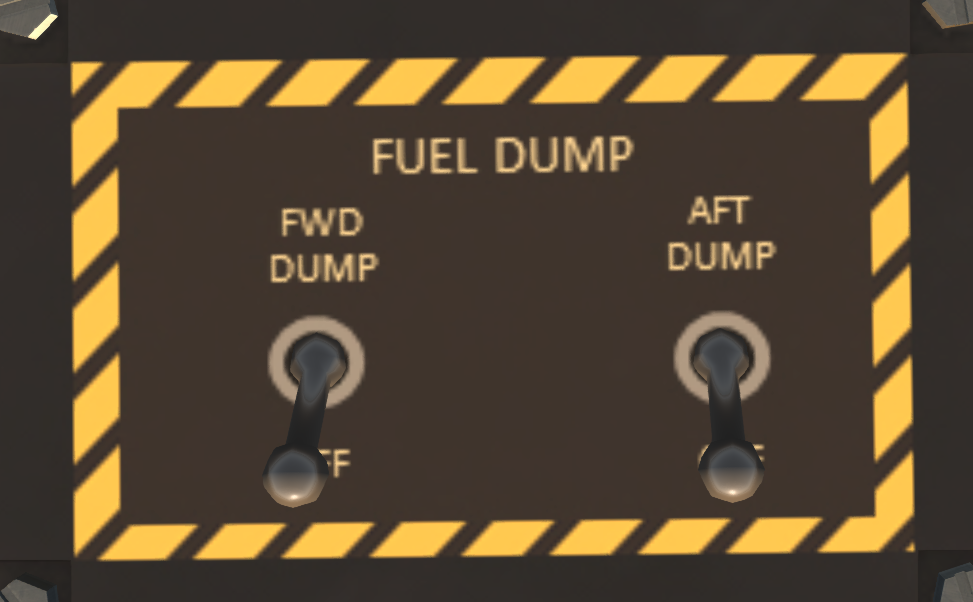
The S61 is equipped by a fuel dump system to dump fuel in flight from the main tanks. The dump system is controlled through the fuel dump control panel shown in Figure 25. The fuel dump switches control electric gate valves located off the fuel line ahead of the fuel filter. When conducting a dump, at least one boost pump in the target tank must be operating. Fuel can only be dumped from the main tanks. To dump fuel from an auxiliary tank, the fuel must first be transferred from the auxiliary to the main tank. Dumped fuel is expelled through a tube located at the back of the right sponson. The dump system is capable of dumping 140 pounds/min from each side.
5.11 Fuel Drain Ports
There are 8 fuel drain ports on the underside of the aircraft: one for each auxiliary tank, two for each main tain, and one for each fuel filter. The drain ports should be checked before each flight to ensure the fuel is contaminant free. Drained fuel should be clear and have an oily smell. If there is a blue or red tint to the fuel, do not fly or start the engines. A blue or red tint indicates that the tank is contaminated with aviation gasoline. If contaminated fuel is found, the tank should be flushed before the next flight.
6 Flight Controls and AFCS
6.1 Flight Controls
The helicopter is controlled by changing the pitch of the blades collectively or cyclically. Pitch changes are made through the flight controls which include a collective, a cyclic control stick and anti-torque pedals. The pilot and copilot controls are interconnected and move together. The collective increases the pitch of all blades, controlling the helicopter vertically. The anti-torque pedals control the pitch of the tail rotor, thus changing the tail rotor thrust. The cyclic imparts unequal pitch around the blade disk to redirect thrust laterally or longitudinally. See SECTION 1 - General for details on the Second-Life control options for the controls.
6.2 AFCS
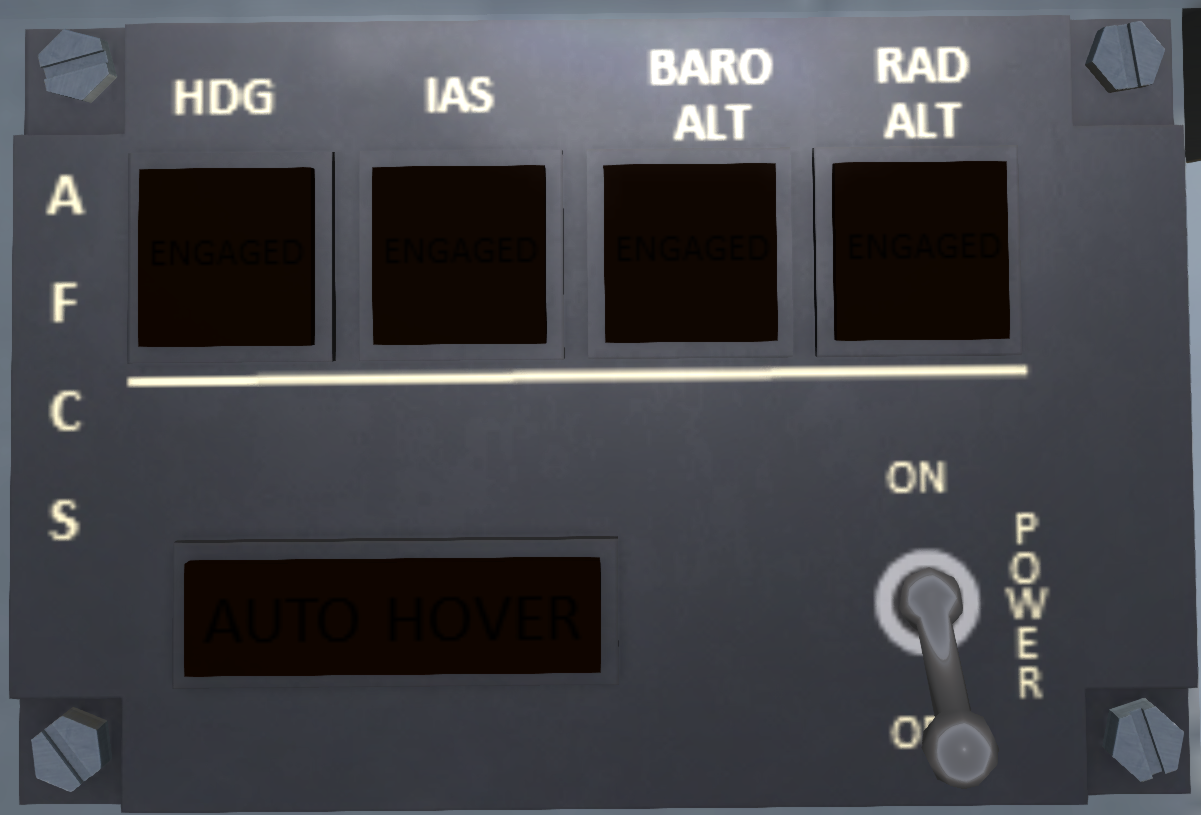
The Advanced Flight Control System (AFCS) can be used to reduce pilot workload by maintaining one or more flight axes of the helicopter. It can be used to maintain airspeed, heading, altitude or any combination of these. The system is comprised of an AFCS computer, a doppler radar system, sensors, channel monitor, an afcs indicator, actuators and a common AFCS control panel (see )
At the top of the AFCS panel are four "hold" buttons. Turning on a hold causes the selected flight axis to be maintained automatically by the AFCS. The following four holds can be maintained:
| Button | Effect |
|---|---|
| HDG | Holds heading. Below 40 knots, heading will be maintained with pedals, and above 40 knots with lateral cyclic. When enaged, the current heading will be held. You can change the heading either through chat command, or by turning the heading bug on the HSI. |
| IAS | Holds the Indicated Airspeed you were maintaining when the button was engaged. The held airspeed can be changed through chat commands. |
| BARO ALT | Holds the barometric altitude (above MSL) at the time you engaged the hold. Target altitude can be changed through chat commands. |
| RAD ALT | Holds the radar altitude (above ground level) at the time you engaged the hold. Radar altitude can only be used to the limit of the radar altimeter. Target altitude can be changed through chat commands. |
In addition to the hold buttons is an AUTOHOVER button at the bottom of the AFCS panel. Engaging AUTOHOVER will set holds on heading, airspeed and altitude and set the hold airspeed to zero. Pressing AUTOHOVER again while already in an autohover will disengage the autotpilot.
6.3 AFCS Chat Commands
The following chat commands can be used with the AFCS:
| Command | Description |
|---|---|
| ap IAS | Toggle airspeed hold |
| ap ALT | Toggle altitude hold |
| ap RALT | Toggle radar altitude hold |
| ap HDG | Toggle heading hold |
| ap HVR | Enter autohover mode |
| ap DIS | Disconnect autopilot |
| ap IAS n | Set the target airspeed to n |
| ap HDG n | Set the target heading to n |
| ap L n | Set the target heading left by n degrees |
| ap R n | Set the target heading right by n degrees |
| ap ALT n | Set the target altitude to n feet |
| ap RALT n | Set the target altitude to n feet above ground |
| ap D n | Set target altitude up n feet |
| ap U n | Set target altitude down n feet |
| ap to | Take off to a low hover then enter autohover |
| ap land | Autoland aircraft. |
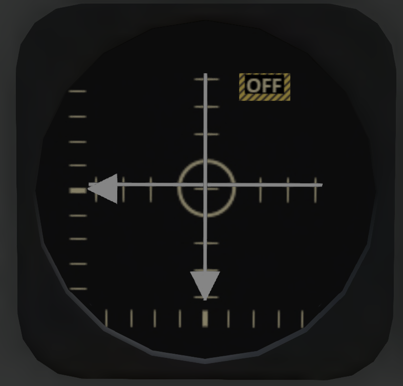
6.4 AFCS Indicator
An AFCS indicator gauge (see Figure 28) is mounted on the pilot and co-pilot sides of the main instrument panel. The gauge takes input from the AFCS and displays any movement of the helicopter from a stable hover. The AFCS and doppeler radar systems must be on for the AFCS indicator to function, but the AFCS does not need to be engaged. The vertical and horizontal needles show lateral and longitudinal movement relative to the ground, respectively. When the needles are centered, there is no lateral or longitudinal movement of the helicopter. The more the deflection of each needle, the higher the ground movement is. When a needle is deflected, the cyclic must be moved in the direction of the needle to stop movement of the helicopter.
The triangle indicator on the bottom of the indicatorwith a horizontal scale shows yaw motion. The more the triangle is deflected from the center, the faster the the yaw motion of the helicopter. Press the anti-torque pedal opposite the arrow deflection to stop yaw motion and center arrow.
The triangle indicator on the left side of the indicator with the vertical scale reflects vertical motion of the helicopter. The amount of deflection indicates he amount of vertical movement. Apply collective in the opposite direction of the deflection to recenter the needle and stop vertical movement.
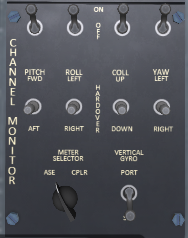
6.5 Channel Monitor Panel
The AFCS outputs commands on four channels: pitch (longitudinal cyclic), roll (lateral cyclic), collective and yaw. The channel monitor panel (see Figure 29, located on the pilot's side console, modulates these outputs and allows information on one or more channels to be disabled in the event of a partial AFCS failure. In normal operation, the channel switches at the top of the panel should all be left in the ON position. Moving a switch to the OFF position will disable output from the AFCS on the indicated channel.
Each channel also has a three-position hardover switch. These switches are normally left in the center OFF position. Moving a hardover switch forward or back will force output on the AFCS channel in the indicated direction.
A channel monitor test switch, located on the upper panel, can be used to test the channel monitor. When the AFCS is on, and the channel monitor test switch is in TEST mode, the control output on each channel will cycle back and forth slowly over a small displacement. Turnning off a channel switch will stop movement on the affected channel.
The channel monitor panel also includes a switch labeled VERTICAL GYRO. The vertical gyro is used to send pitch and roll information to the AFCS. The helicopter is equipped with a port and a starboard gyro. In the event one of these gyros fail, use this switch to select the other gyro.
A METER SELECTOR knob can be used to select the information that is displayed on the AFCS indicator. In normal operation only the ASE position should be used.
6.6 Doppler
The autopilot/AFCS gets its lateral movement information through a doppler radar system. The doppler system is controlled by a panel (see Figure 30) on the middle console. A green indicator light on the doppler panel shows when the system is powered and functioning. In additional the doppler system has the following four switches:
| Switch | Description |
|---|---|
| ON/OFF | Turns the unit on and off. |
| INCR/DECR | Test switch for longitudinal motion sensing. When in the INCR or DECR positions, a constant "forward motion" or "backward motion" signal will be sent to the AFCS. In normal operation this switch should be in the center position. |
| LEFT/RIGHT | Test switch for lateral motion sensing. When in the LEFT or RIGHT positions, a constant "left motion" or "right motion" signal will be sent to the AFCS. In normal operation this switch should be in the center position. |
| LAND/SEA | This switch controls the sensing mode of the doppler system. When LAND is selecting, motion sensing is optimized for land operation. When SEA is selected, motion sensing is optimized for over-water operations. If the switch position does not correspond to the type of surface the helicopter is flying over, AFCS hover performance over that surface will be degraded. |
7 Hydraulic Systems
7.1 General
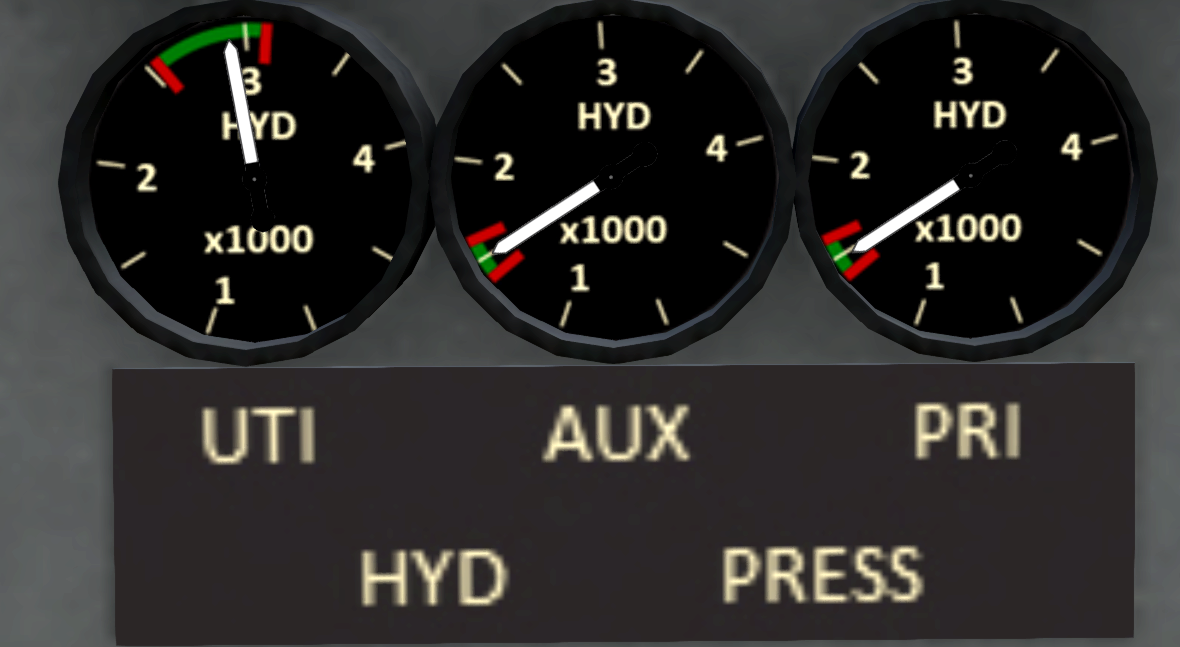
The S-61R has two flight control hydraulic systems (primary and auxiliary) and a utility hydraulic system. All hydraulic pumps are powered by the main transmission accessory drive which is powered by either engine or by the APU. Engine and/or APU must be at above 70% RPM for hydraulic pressure to be available. A bank of three pressure gauges shows the pressure of each system (see Figure 31).
7.2 Flight Control Hydraulics
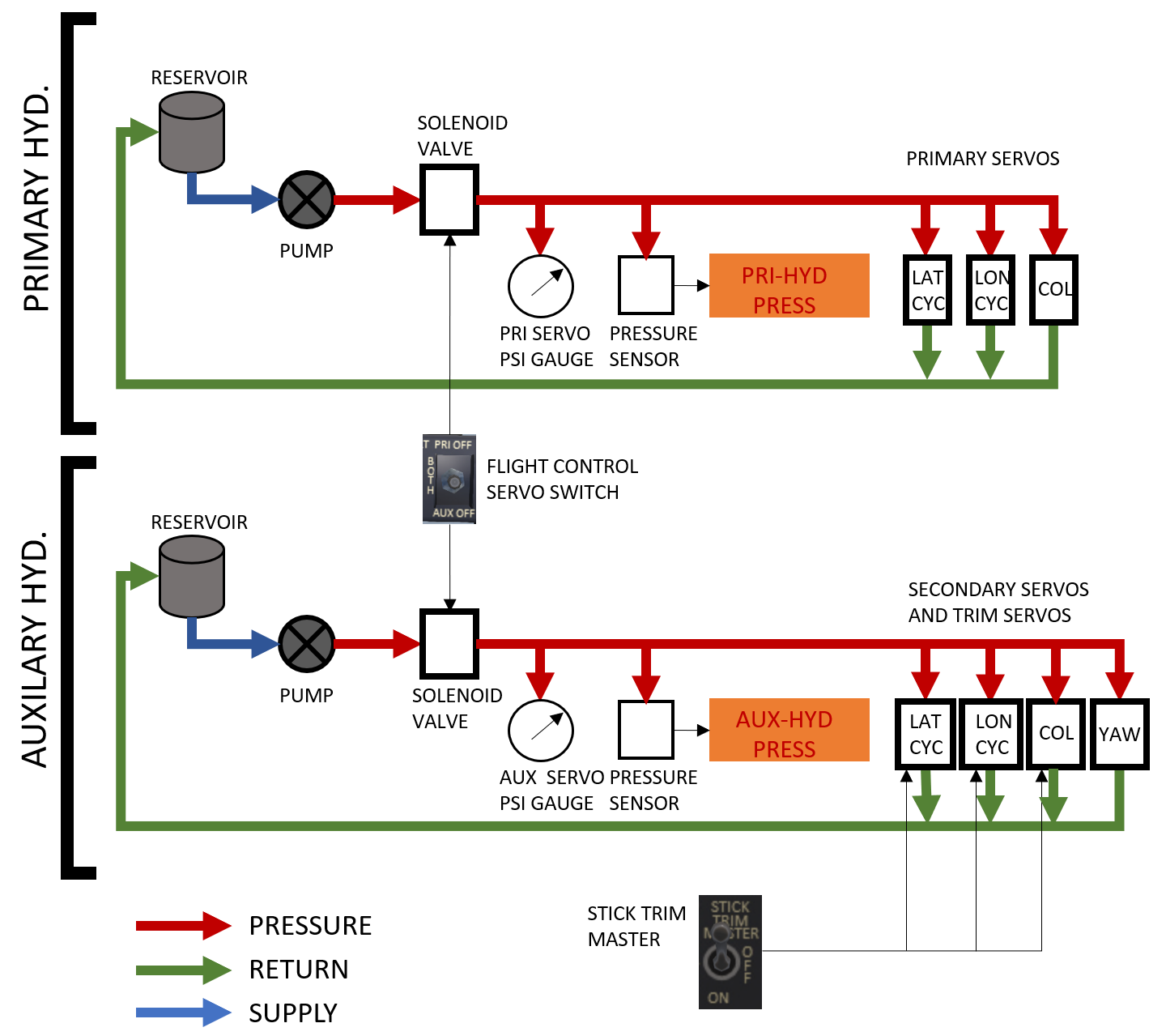
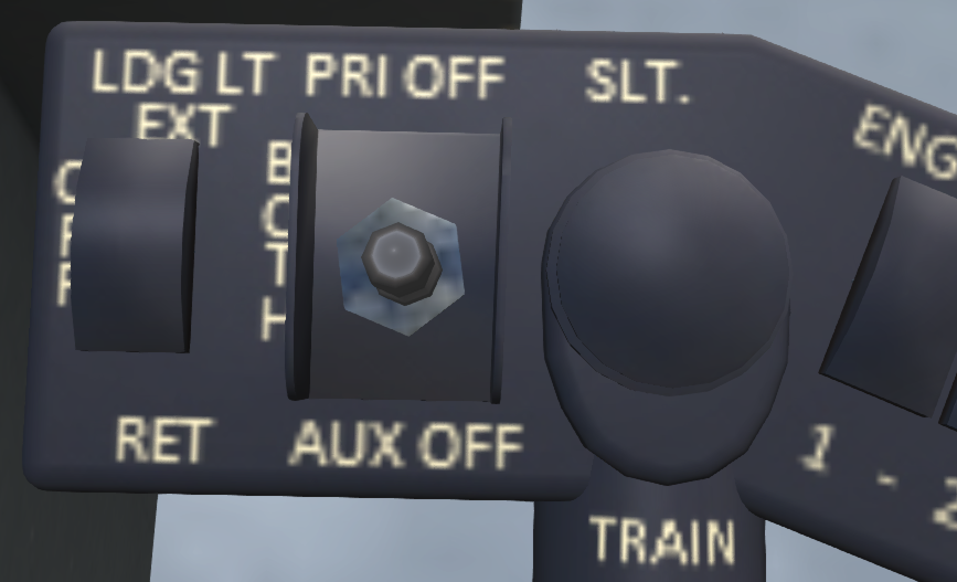
The primary and auxiliary hydraulic systems (see Figure 32) provide boost power to operate the flight controls. The flight servos also limit feedback of vibration in the rotor system to the flight controls. These act in conjunction with the direct linkages from the flight controls to the swash plate to reduce the forces needed to actuate the controls. Each system operates independently and operates a similar set of servos. In normal operation, both systems are in use during flight. In the event that one of the systems fails, the affected system should be shut off with a switch on the collective (see Figure 33) to relieve the excessive control forces the drag produced by the failed system.
7.2.1 Primary Hydraulic System
The primary hydraulic system powers three hydraulic servo units that control the main rotor swash plate for cyclic and collective control inputs. The primary hydraulic system does not provide any boost or damping for the anti-torque pedals. A low pressure sensor detects when the hydraulic pressure is inadequate and illuminates a PRI-HYD PRESS warning light on the warnings and alerts panel. A pressure gauge on the main panel also shows the pressure available in the system. The primary hydraulic system is feed by a 1.8 quart reservoir located in the rear portion of the engine and transmission compartment.
7.2.2 Auxiliary Hydraulic System
The auxiliary hydraulic system powers four hydraulic servo units, three that control the main rotor swash plate for cyclic and collective control inputs, and a fourth servo unit driving the anti-torque pedals. The auxiliary system also handles cyclic trim and the AFCS. A low pressure sensor detects when the hydraulic pressure is inadequate and illuminates a AUX-HYD PRESS warning light on the warnings and alerts panel. A pressure gauge on the main panel also shows the pressure available in the system. The auxiliary hydraulic system is feed by a 1.8 quart reservoir located in the rear portion of the engine and transmission compartment. Note that the auxiliary hydraulic system must be functioning for AFCS use.
When the auxiliary hydraulic system is active, and the STICK TRIM MASTER switch on the overhead console is ON, the following fine control chat commands are enabled:
| Command | Description |
|---|---|
| fc | Toggles fine control on/off. |
| fc0 | Turns off fine control. |
| fc1 | Turns on fine control. |
| fc2 | Turns on very fine control. |
7.3 Utility Hydraulic System
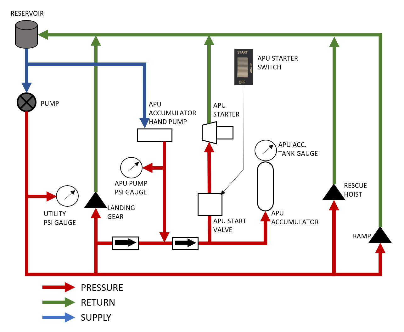
The utility hydraulic system (see Figure 34) provides pressure to all hydraulic systems other than the flight controls. A 3000psi pump drives the system. Hydraulic fluid is held in a 5.03 quart reservoir located in the aft of the engine and transmission compartment. A pressure indicator in the cockpit (see Figure 31) indicates the current pressure in the system.
The utility hydraulic system provides pressure for the following systems:
- Landing gear
- Ramp
- Hoist
- Cargo hook
- APU starter/accumulator
8 Power Train System
Engine power is supplied to the rotors through a mechanical transmission system. This system consists of a main transmission, and intermediate and tail rotor gear boxes. An overruning sprag clutch for each engine in the main transmission allows the rotor system to continue turning in the event of an engine failure. The main transmission includes an accessory section which drives the hydraulic pumps and generators; and a main drive section which drives the main rotors. An output shaft from the main rotor drives an intermediate gearbox at the base of the tail, which in turn drives a tail rotor gearbox at the top of the tail which ultimately drives the tail rotor.
The transmission can be monitored from the cockpit through pressure and temperature gauges as well as alert lights indicating when tolerances are exceeded. The main transmission temperature and pressure gauges are mounted on the center portion of the main panel (see Figure 3, Item 6). Each transmission system includes a chip detector. The chip detector consists of two magnetized electrodes. Any metal particles in the lubrication system will collect on the electrodes and bridge the gap forming an electrical connection. This will a trigger the chip warning light on the warning and alert panel in the cockpit. The chip lights are XMSN CHIP MAIN, XMSN CHIP INTMED and XMSN CHIP TAIL for the main, intermediate and tail-rotor transmissions, respectively. The main transmission also has two additional warning lights for the main transmission oil temperature and pressure, XMSN OIL HOT and XMSN OIL PRESS.
9 Rotor System
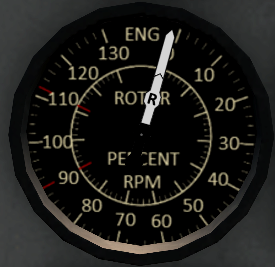
Lift is produced by a single counter-clockwise rotating main rotor with five blades. A five blade tail rotor produces thrust for yaw and to counter-act torque from the main rotor. Rotor RPM is displayed on a tachometer (in percent RPM) on the pilot and copilot sides of the console along with the engine RPM (see Figure 1, Item 12).
9.1 Inflight Blade Inspection System
The main rotor blades are equipped with an Inflight Blade Inspection System - IBIS, this system alerts the pilot to damage to the rotor blades that may signal an impending failure of the rotor system. IBIS consists of pressurized main rotor blades, a trip mechanism at the root of each main rotor blade, a detector on the aircraft and a BLADE PRESS warning light on the caution light panel. In the event of any damage to a rotor blade, such as cracks in the blade, the blade will depressurize, activating the trip mechanism. The trip mechanism then exposes a tiny radioactive source that is detected by the detector on the aircraft, which then illuminates the BLADE PRESS warning light. In the event the BLADE PRESS warning light illuminates, an immediate landing should be made.
10 Electrical System
10.1 Overview
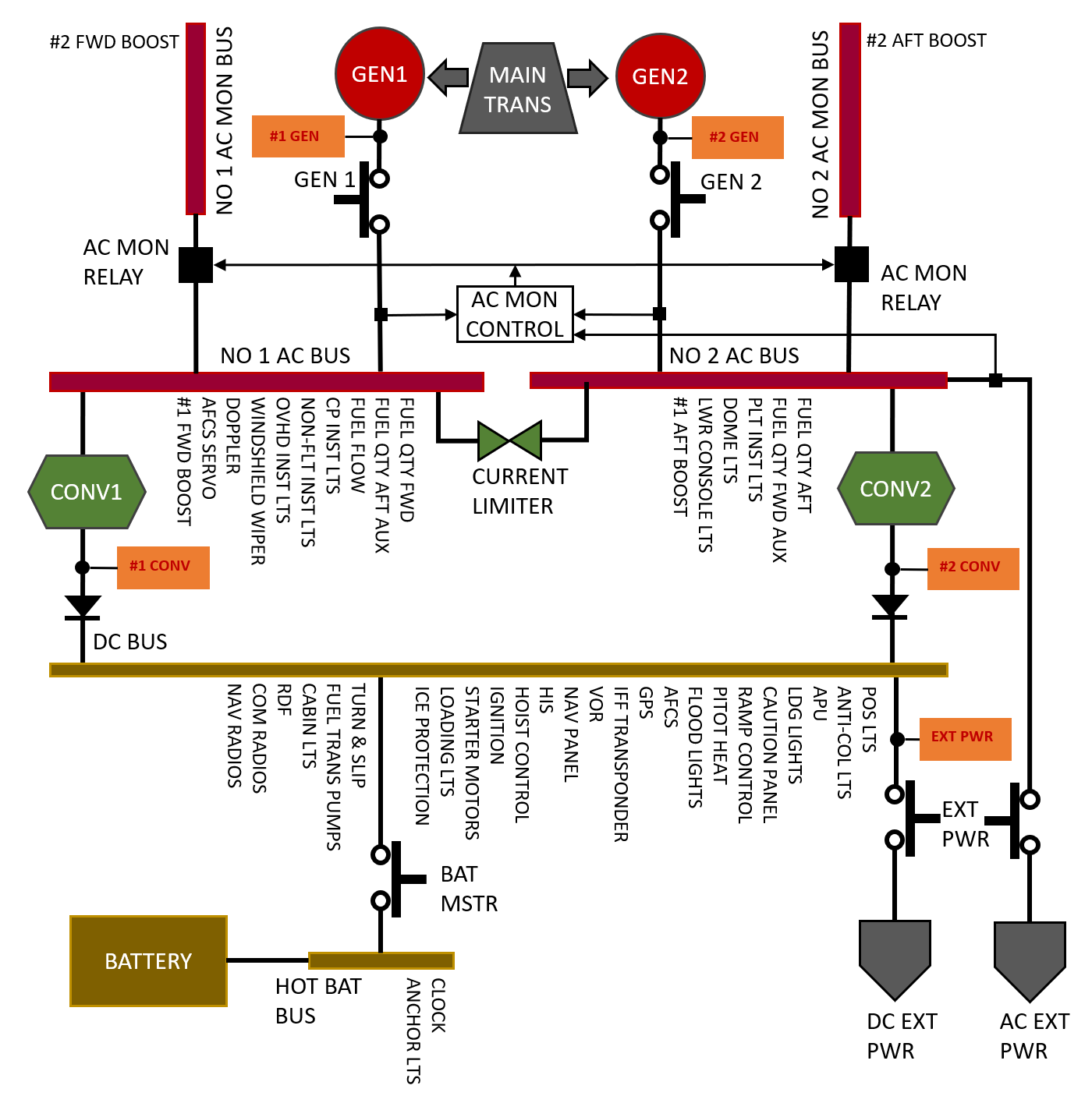
The S-61R electrical system (see Figure 35) consists of two AC buses, two AC monitor buses, a DC bus, and a hot battery bus. Each AC bus is powered by a 115V, 400 Hz generator. The AC buses are connected by current limiters. In normal operation, both buses can be powered by either generator, but in the event of a short on one of the buses, the current limiters will allow the other bus to continue to function normally. Connected to each AC bus though a relay is a monitor bus. A control circuit will disconnect both monitor buses unless both AC generators are producing power. If either generator is off, damaged, or there is a short on one of the AC buses, the monitor buses will disconnect.
The DC system operates at 28 volts when powered through converters from either AC bus, or from a 24-volt nickel-cadmium battery. The hot battery bus supplies power to several devices even when the BATT switch is OFF. These devices include the digital clock and the anchor light.
The table below summarizes the electrical buses in the S-61R:
| Bus | Powered By |
|---|---|
| Battery Hot Bus | Battery (At all times) |
| DC Bus | DC Converters 1 & 2 or Battery (with battery switch on) |
| #1 AC Bus | #1 Generator (#2 will power if #1 fails) |
| #2 AC Bus | #2 Generator (#1 will power if #2 Fails) |
| #1 AC Monitor Bus | #1 AC Bus (Dropped if either generator fails) |
| #2 AC Monitor Bus | #2 AC Bus (Dropped if either generator Fails) |
10.2 Electrical Panel
The electrical system is controlled through a set of 6 switches on the overhead panel (see Figure 36). A switch labeled BATTERY energizes the DC bus from the battery when turned ON.
| Switch | Description |
|---|---|
| BATTERY | Energizes the DC bus from the 28V DC battery |
| GEN1/GEN2 | Enables the generators for each AC bus. The main transmission accessory section must be powered by an engine or the APU for the generators to produce power. |
| CONV1/CONV2 | Energizes the DC bus by converting power from an AC bus |
| EXT PWR | Enables external power to all buses. |
10.3 External Power
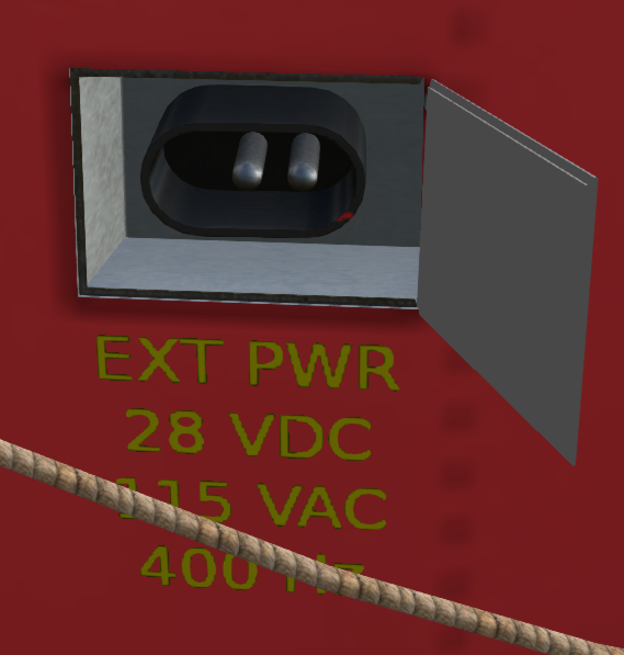
An external power port is located at the front of the aircraft on the right-hand side (see Figure 37). A Ground Power Unit (GPU) can be connected to this port to provide DC and AC power on the aircraft. In addition to connecting the ground power unit, the EXT PWR switch in the cockpit must also be ON in order for external power to be available in the aircraft. To recharge the battery, the BATTERY switch must also be on. When external power is connected and turned on a green EXT PWR advisory light will illuminate in the cockpit.
11 Ramp
The S-61R is equipped with a rear ramp consisting of two independently controllable sections, the forward ramp and the aft ramp. The forward ramp hinges directly to the floor of the helicopter, extending the main cabin floor area when the ramp is in the up position. The aft ramp shares a hing on the aft side of the forward ramp. When both ramps are in the closed position, the helicopter aft cabin is closed off by the ramp. When both ramps are in the open position, the ramp can be used for loading the helicopter. There is also an emergency release for the aft ramp that allows it to be used as an emergency exit. The ramp system operates off the utility hydraulic system. The ramp can be controlled from a panel next to the pilot on the middle console or through a panel in the aft area of the aircraft. The Aft ramp may be opened in flight or on water, the forward ramp may only be opened on the ground.
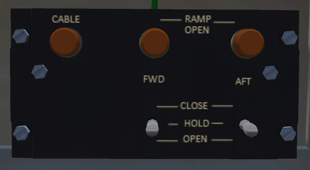
11.1 Pilot Ramp Control Panel
The pilot ramp control panel (see Figure 38) includes the following three switches:
| Switch | Description |
|---|---|
| MASTER | Master switch for the ramp system. Has OFF, PILOT and CREW positions. When in the PILOT position, only the pilot controls are active, and when in the CREW position, only the crew controls are active. The ramp can be disabled by placing this switch in the OFF position. The emergency release will still be active even when this switch is OFF. |
| FWD | Forward ramp control. Has OPEN, HLD and CLOSE positions. In the OPEN position the forward ramp will move toward the open position until it is fully open. In the HLD position, the forward ramp will hold the current position. And in the CLOSE position the forward ramp will move toward its closed position until it is fully closed. |
| AFT | Aft ramp control. Has OPEN, HLD and CLOSE positions. In the OPEN position the aft ramp will move toward the open position until it is fully open. In the HLD position, the aft ramp will hold the current position. And in the CLOSE position the aft ramp will move toward its closed position until it is fully closed. |
In addition to the three switches, the ramp control panel includes two indicator lights above each ramp control switch. These indicator lights will illuminate when the ramp corresponding to its switch is in motion.
11.2 Crew Ramp Control Panel
The crew ramp control (see Figure 39) has the following switches which are active when the MASTER switch is in the CREW position.
| Switch | Description |
|---|---|
| FWD | Forward ramp control. Has OPEN, HLD and CLOSE positions. In the OPEN position the forward ramp will move toward the open position until it is fully open. In the HLD position, the forward ramp will hold the current position. And in the CLOSE position the forward ramp will move toward its closed position until it is fully closed. |
| AFT | Aft ramp control. Has OPEN, HLD and CLOSE positions. In the OPEN position the aft ramp will move toward the open position until it is fully open. In the HLD position, the aft ramp will hold the current position. And in the CLOSE position the aft ramp will move toward its closed position until it is fully closed. |
The crew ramp control also includes the following three lights:
| Switch | Description |
|---|---|
| FWD | Indicates when the forward ramp is not fully closed. |
| AFT | Indicates when the aft ramp is not fully closed. |
| CABLE | Never indicates anything. |
12 Crew Access Ladder and Rescue Platform
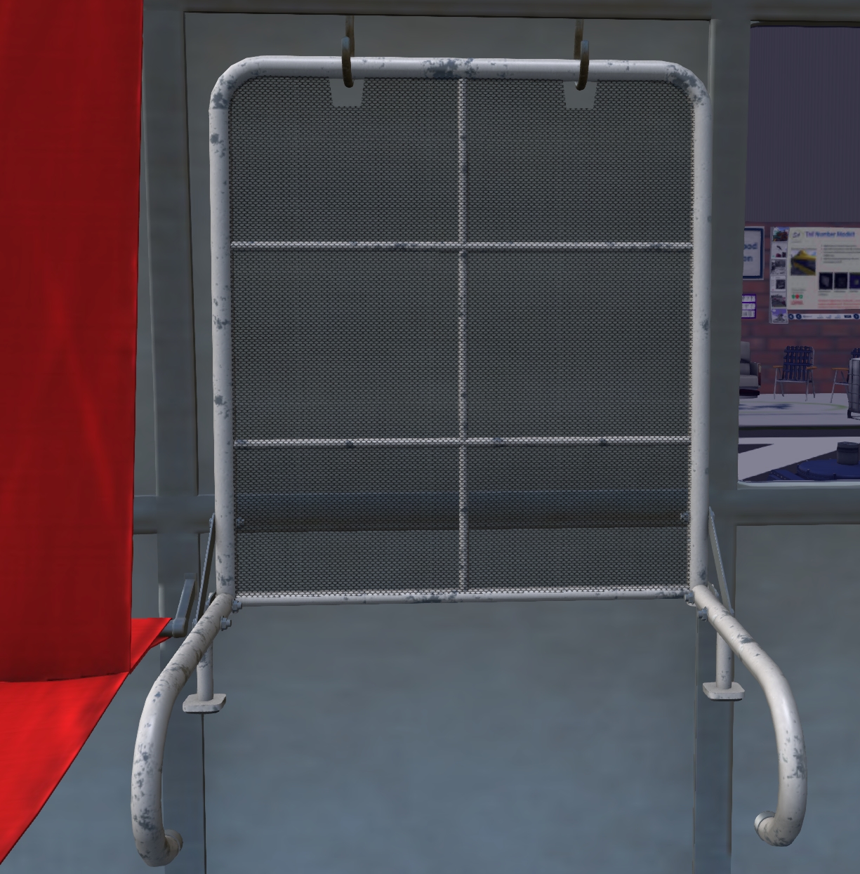
A crew ladder is normally stowed behind the RDF operator seat on the left side of the main cabin (see Figure 40). Click the ladder to deploy it in the main cabin entrance. The door must be open to deploy the ladder. Once deployed it is possible to enter the helicopter by walking toward the ladder.
In addition to the ladder is rescue platform (see Figure 41). The rescue platform is normally stowed near the aft of the aircraft on the right-hand side. Since it also acts as a seat while deployed, you may need to right-click and select Touch in order to touch it. In most cases the rescue platform we deploy or stow when touched. For more details on use of the rescue platform see the SECTION 9. Mission Equipment. For more details on how to use the seating and OnBoard in the S-61R, see SECTION 12. SL Features.
13 Lighting
13.1 Cockpit Lighting
The cockpit lights are controlled through knobs on the overhead panel. Each knob has five intensity levels at OFF, 25%, 50%, 75% and 100% intensities. These lights are described in the following table:
| Light | Power Source | Description |
|---|---|---|
| CO-PILOT FLT INST | AC1 | Co-pilot-side flight instrument lights. These lights are mounted under the dash hood and provide lighting for the co-pilot-side flight instruments. |
| SECONDARY INST | DC | Secondary instrument lights. These lights are mounted overhead behind the pilot seats and illuminate the full instrument panel with red light. |
| LOWER | AC2 | Lower Console Lights. These lights are mounted overhead behind the pilot seats and illuminate the lower console between the pilot and co-pilot seats. This switch controls the white lower console light. |
| LOWER CONSOLE RED LTS | AC2 | Lower Console Red Lights. This light his mounted in the same housing as the LOWER light. It also illuminates the lower console but with red light. |
| OVHD | AC1 | Overhead console light. This light is mounted behind the pilot seats and illuminates the overhead console with red light. |
| NON-FLT INST | AC1 | Non-flight instrument lights. These lights are mounted under the dash hood and provide lighting for the non-flight instruments in the center of the main console. |
| PILOT FLT INST | AC2 | Pilot-side flight instrument lights. These lights are mounted under the dash hood and provide lighting for the pilot-side flight instruments. |
13.2 Main Cabin Lighting
| Light | Power Source | Description |
|---|---|---|
| EMER EXIT LTS | DC/Internal Battery | Emergency Exit Lights. Several emergency exit lights are mounted throughout the aircraft to provide illumination for safe egress in the event of an accident. These lights contain their own power source and do not need aircraft power to function. They are controlled through a three-position switch on the upper console labeled EMER EXIT LTS with TEST, OFF and ARM positions. In the TEST position, all emergency lights will illuminate. Use this to test if the lights are functioning and the internal batteries are charged. In the ARM position, the lights will trigger after an impact or hard landing. If the lights illuminate in the ARM position, click one of the emergency light fixtures to reset it. |
| CABIN LIGHTS | DC | Main Cabin Lights. These lights are mounted in four separate fixtures on the ceiling in the main cabin. They are controlled through a switch on the RDF operator console with RED, OFF and WHITE positions. |
13.3 Exterior Lighting
A summary of the exterior lights are shown in Figure 43. Each of the exterior lights are discussed in the following table and are controlled by the panel shown in Figure 44.
| Light | Power Source | Description |
|---|---|---|
| ANCHOR | Battery Hot | Anchor Lights. The lights should be used anytime the aircraft is anchored. These lights are designed to operate off the hot battery bus and will operate even when the main BATTERY switch is OFF. |
| FUSELAGE | DC | Fuselage Lights. A white fuselage is mounted on the top and bottom of aircraft. The fuselage light is used to make the aircraft more visible for night formation flying. The fuselage light is controlled by a 3-position switch with DIM, OFF and BRT (bright) positions. |
| ANTI-COLLISION | DC | Anti-Collision Lights. The anti-collision lights should be on any time a rotor is moving warn others of the danger, and in flight to improve aircraft visibility. There are two anti-collision lights, each controlled by a separate switch: a forward anti-collision light mounted on the underside of the aircraft, and and aft anti-collision light mounted on the top of the vertical stabilizer. The forward anti-collision light should be turned off prior water landings. |
| POSITION | DC | Position Lights. Position lights should be used between sunset and sunrise and during total solar eclipses. The white position is mounted on the back of the vertical stabilizer, the red position light is mounted on the left sponson, and the green position light is mounted on the right sponson. The position lights are controlled by a mode switch and a brightness switch. The mode switch has positions STEADY, OFF, and FLASH. A separate brightness switch has positions DIM and BRT (bright). When the mode switch is off, the brightness switch is ignored. |
| HOVER | DC | Hover Lights. Five hover lights improve visibility around the aircraft while hovering at night. Two lights are mounted under each sponson, one light on the belly, and two additional lights on the nose. The hover lights are controlled by a two-position switch. |
| LOADING | DC | Loading Light. Located under the tail boom behind the main ramp. This light is used to assist in loading by ramp at night. This light is controlled by an additional switch labeled LOADING below the main set of exterior light switches. This switch controls both an external loading light, and an interior loading light over the ramp on the interior of the helicopter. |
| SEARCH | DC | Search Light. A steerable search light is mounted in the battery door. This light is controlled by a switch with STOW, OFF and ON positions. In the OFF position, the light will not illuminate, but the light gimbal will remain in its current position. In the ON position, the light will illuminate and a joystick on the center console (see Figure 45) can be used to aim the light. Use the chat command "jdir spotLightControl" to move the spotlight through chat commands (where dir is one or more of f,b,r,l for forward, back, right, left). Each chat command will move the control in that direction for a brief time, then return it to center. |
14 Caution - Advisory Panel
The Caution - Advisory Panel (see Figure 46) is located in the center of the main panel and contains an array of indicator lights indicating potential malfunctions or alert conditions in the helicopter. A complete list of all the lights and their meanings are shown in Appendices. A switch on the bottom with DIM and BRT setting can select the brightness of the lights. There is also a push button in the lower left corner that can be used to test the alert lights.
In addition to the main bank of lights, there is an additional MASTER CAUTION and FIRE light mounted on the edge of dash hood. The MASTER CAUTION light will illuminate when any of the caution lights illuminate. You can touch the MASTER CAUTION light to make it go out until any new alerts are posted. The FIRE light will go on when any engine or APU fire warning lights is triggered.
