Difference between revisions of "S-61R Pelican/All Weather Operations"
(→Utility Systems) |
|||
| Line 1: | Line 1: | ||
<span class=sa-section>SECTION 12. ALL-WEATHER OPERATIONS</span> | <span class=sa-section>SECTION 12. ALL-WEATHER OPERATIONS</span> | ||
| − | === | + | === Weather in the S-61 === |
| + | |||
| + | The S-61 includes support for Weather 2.0 as described in [[SL_Helicopter_Flying_Handbook/Weather|The SL Helicopter Flying Handbook - Weather]]. The remainder of this section describe the various systems in the S-61 that support flying in adverse weather conditions. | ||
| + | |||
[[File:s61-anti-ice.png|thumb|right|150px| | [[File:s61-anti-ice.png|thumb|right|150px| | ||
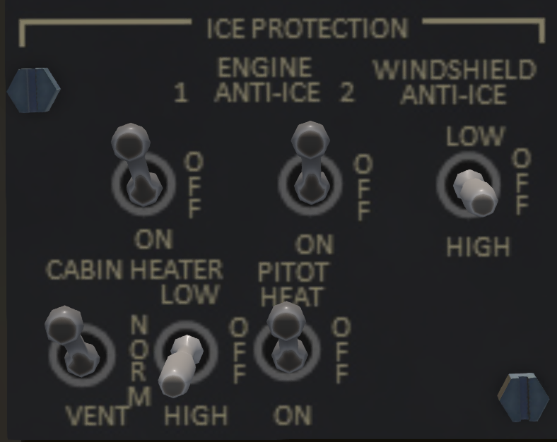
<figure id="fig:antiice"><caption>Ice Protection</caption></figure> | <figure id="fig:antiice"><caption>Ice Protection</caption></figure> | ||
Revision as of 05:21, 1 January 2022
SECTION 12. ALL-WEATHER OPERATIONS
Contents
1 Weather in the S-61
The S-61 includes support for Weather 2.0 as described in The SL Helicopter Flying Handbook - Weather. The remainder of this section describe the various systems in the S-61 that support flying in adverse weather conditions.
1.1 Ice Protection
Ice protection systems are controlled through a panel on the overhead console (see Figure 1). These systems are described in the following sections.
1.1.1 Engine Anti-Ice
The engine anti-ice systems is comprised of a set of sensors and heaters in each engine inlet. The purpose of the system is to prevent ice from forming at the engine inlets and possibly being ingested by them. When the anti-ice system is engaged, the #1/#2 ENG-IVE ANTI-ICE advisory light for the affected engine will illuminate. Also, while the anti-ice system is engaged, and the inlet temperature is below 38C, the #1/#2 INLET ANTI-ICE warning light will illuminate. When first turning on the anti-ice switch, the #1/#2 INLET ANTI-ICE warning light may illuminate until the inlet surface temperatures warm up above 38C. It is also possible for the #1/#2 INLET ANTI-ICE warning lights to come on in extremely cold temperatures if the inlet surfaces cannot be warmed above 38C. The anti-ice system for the #1 engine operates off the #1 AC bus, while the anti-ice system for the #2 engine operates of the #2 AC bus. The engine anti-ice system should be engaged with the OAT is below 5C.
1.1.2 Windshield Anti-Ice
A windshield anti-ice switch labeled WINDSHIELD ANTI-ICE with positions LOW, OFF and HIGH positions is located as part of the ICE PROTECTION subpanel. The system provides ice protection to the pilot and co-pilot sides of the windshield. The co-pilot side anti-ice system is powered by the #1 AC bus while the pilot side anti-ice system is powered by the #2 AC bus.
1.1.3 Pitot Heat
A pitot heat switch labeled PITOT HEAT with positions OFF and ON positions is located as part of the ICE PROTECTION subpanel. The system provides ice protection to the pilot and co-pilot pitot tubes. The co-pilot side anti-ice system is powered by the #1 AC bus while the pilot side anti-ice system is powered by the #2 AC bus.
1.1.4 Cabin Heat
(RP Only) The cabin heat switches are located in the ice protection subpanel. Left left two-position switch under CABIN HEATER has positions ON and VENT. When in the VENT position, the heater is disabled and only air venting is enabled. When the switch is in the ON position, the heater will operate at LOW, NORM (normal) or HIGH power depending on the three-position switch next to the ON/VENT switch.
1.2 Windshield Washer
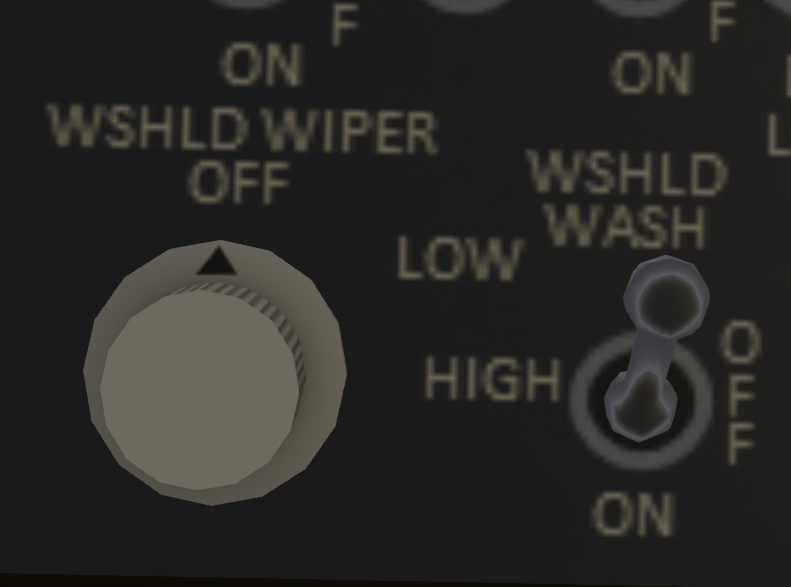
(RP Only) A windshield washer switch labeled WSHLD WASH controls the windshield washer fluid.
1.3 Windshield Wipers
The windshield wipers are controlled by a knob on the upper console (see Figure 2) labeled WSHLD WIPER with positions OFF, LOW and HIGH. The windshield wiper system is powered by the #1 AC bus.

