Difference between revisions of "H-160/Servicing"
(→REFUELING) |
(→AVIONICS) |
||
| (33 intermediate revisions by the same user not shown) | |||
| Line 4: | Line 4: | ||
This section describes all servicing and repair procedures for the H-160. | This section describes all servicing and repair procedures for the H-160. | ||
| − | + | [[File:H160-fuelCap.png|thumb|left|200px| | |
| − | [[File:H160-fuelCap.png|thumb|left| | ||
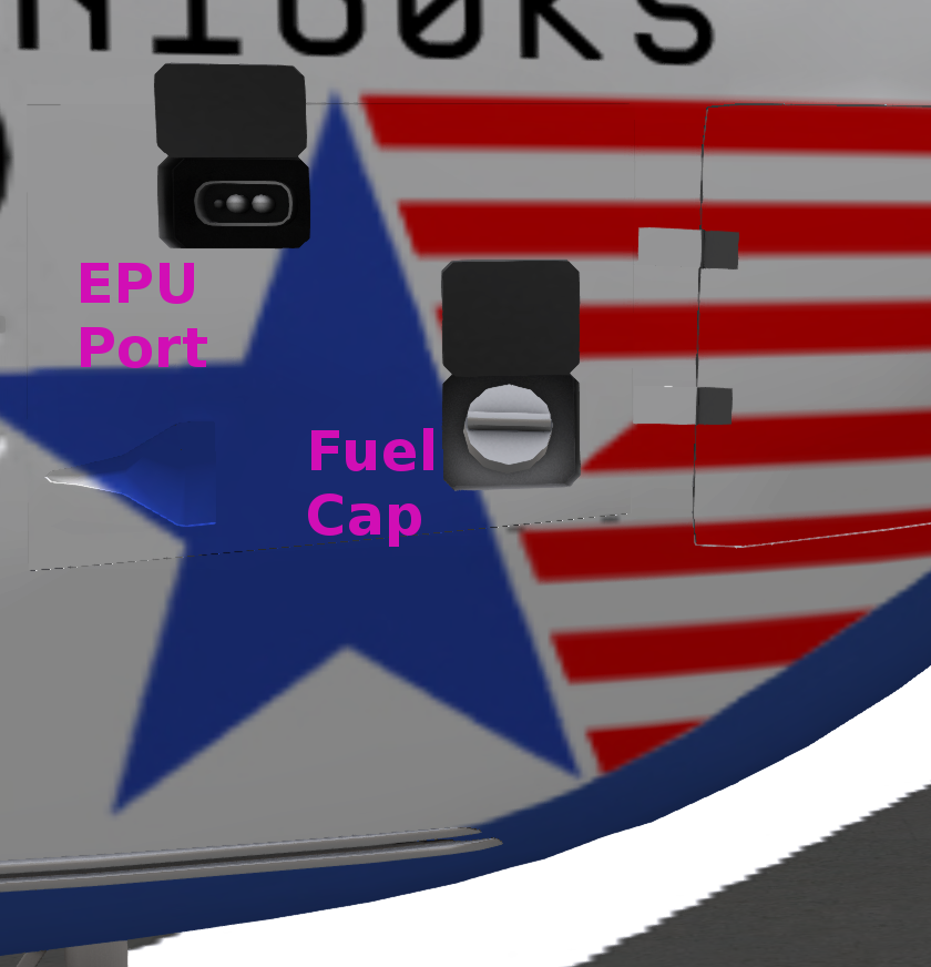
<figure id="fig:fuelCap"><caption>Fuel Cap and EPU Port</caption></figure>]] | <figure id="fig:fuelCap"><caption>Fuel Cap and EPU Port</caption></figure>]] | ||
| + | [[File:H160-covers.jpg|thumb|right| | ||
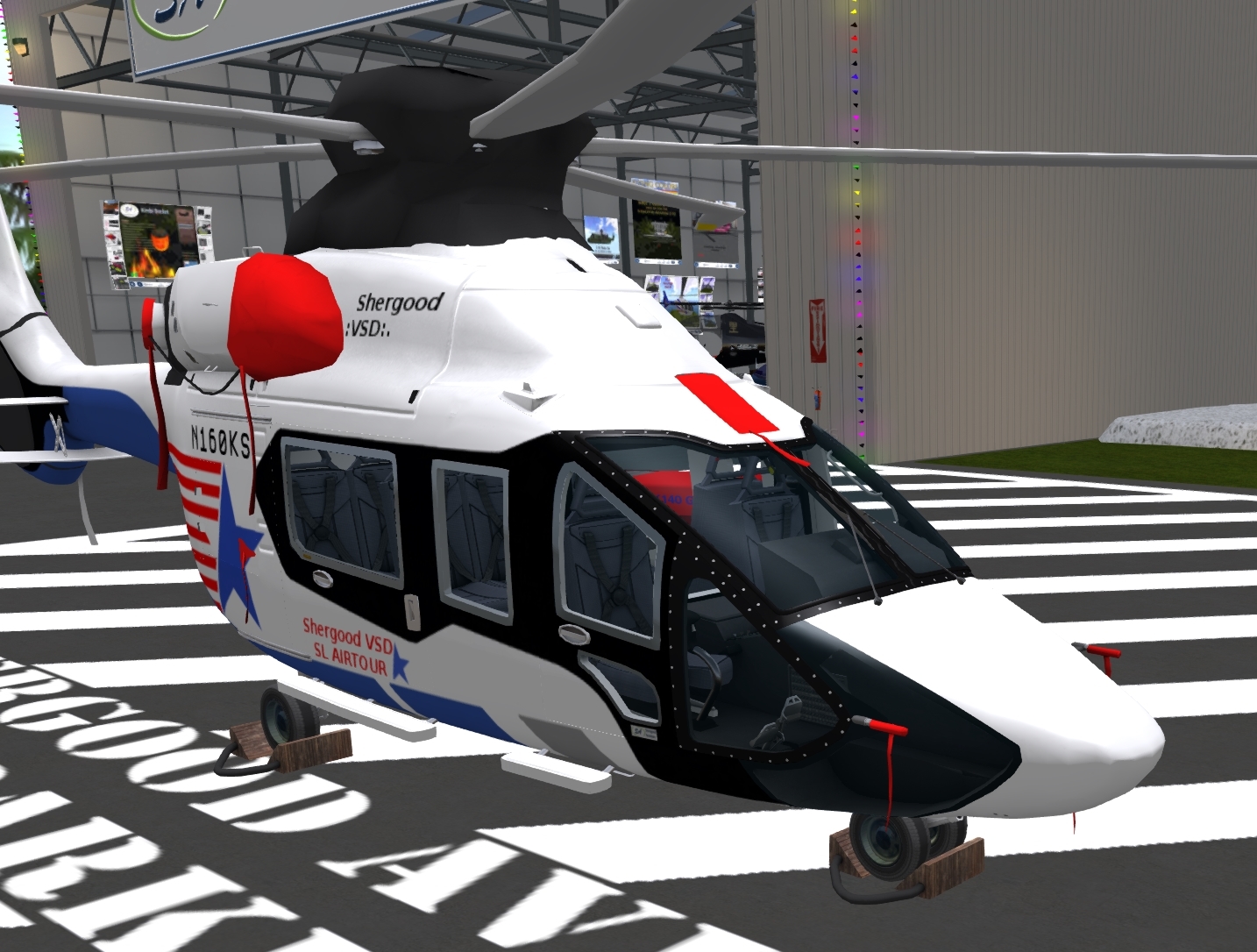
| + | <figure id="fig:covers"><caption>Covers and Chocks</caption></figure>]] | ||
===REFUELING=== | ===REFUELING=== | ||
| Line 17: | Line 18: | ||
===COVER AND CHOCKS=== | ===COVER AND CHOCKS=== | ||
| − | |||
| − | |||
| − | |||
When parking your aircraft for an extended period of time, it is recommended that you use the provided covers and chocks (see <xr id="fig:covers"/>). The covers may be applied by selecting the "Covers" option from the @Get submenu. Click the covers again to remove (derez) them. Only the owner is allowed to remove the covers this way. Covers will also automatically derez if the aircraft moves more than 0.01m from its resting position. | When parking your aircraft for an extended period of time, it is recommended that you use the provided covers and chocks (see <xr id="fig:covers"/>). The covers may be applied by selecting the "Covers" option from the @Get submenu. Click the covers again to remove (derez) them. Only the owner is allowed to remove the covers this way. Covers will also automatically derez if the aircraft moves more than 0.01m from its resting position. | ||
| Line 25: | Line 23: | ||
===ENGINES=== | ===ENGINES=== | ||
| − | The engines are located on either side below and just aft of the main rotor transmission. The engine on left side when looking forward is the #1 engine, and the engine on the right side is the #2 engine. Each engine has a cowling that can be opened for access to the internals. Click on an engine to check for damage, or repair any existing damage. | + | |
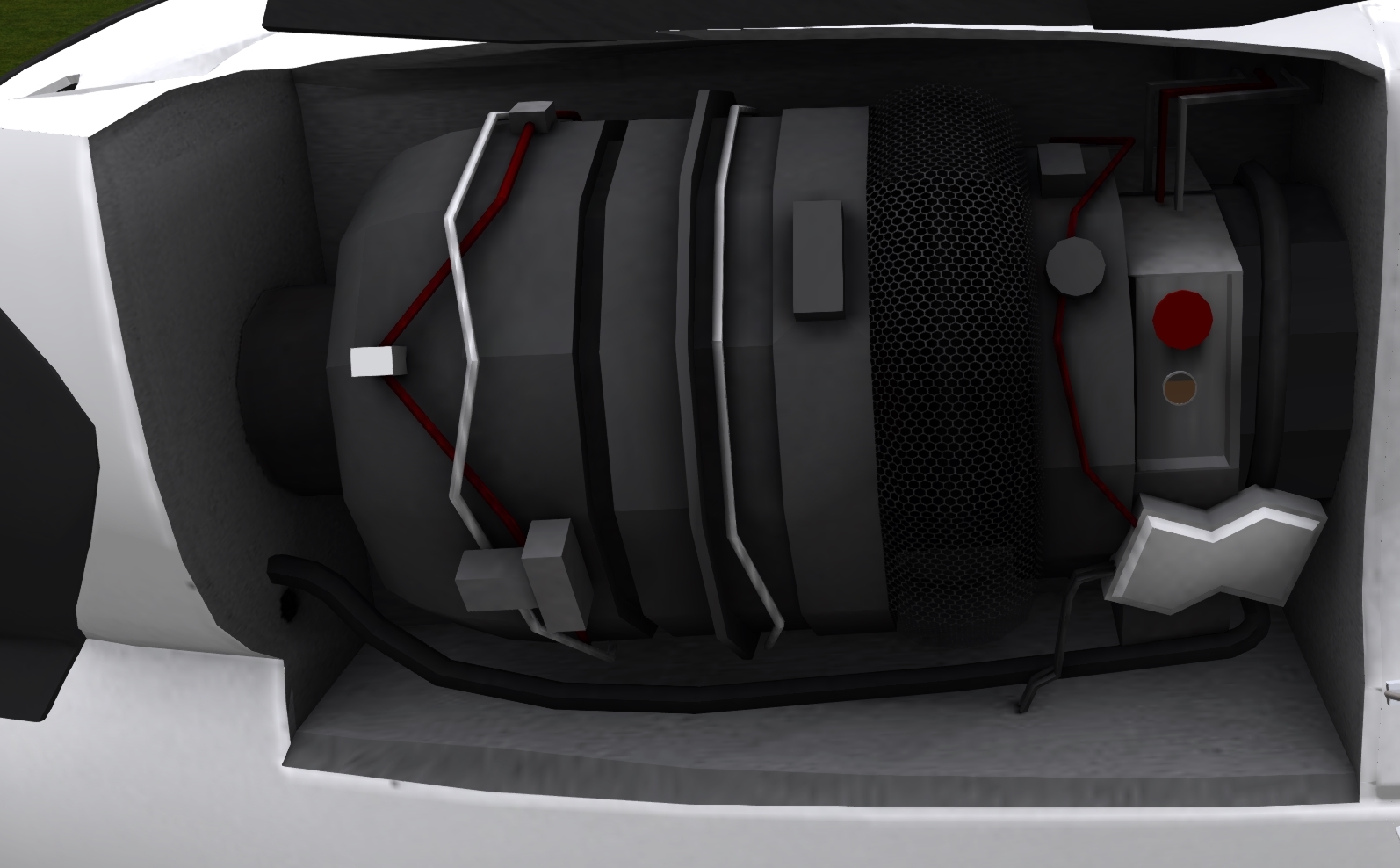
| + | The engines (see <xr id="fig:engine"/>) are located on either side below and just aft of the main rotor transmission. The engine on left side when looking forward is the #1 engine, and the engine on the right side is the #2 engine. Each engine has a cowling that can be opened for access to the internals. Click on an engine to check for damage, or repair any existing damage. | ||
Each engine has an 8 quart oil reservoir. Engines should not be operated with less than 6 quarts. The oil level can be checked with a sightglass below the filler. Click on the red cap to add a quart of oil to an engine. | Each engine has an 8 quart oil reservoir. Engines should not be operated with less than 6 quarts. The oil level can be checked with a sightglass below the filler. Click on the red cap to add a quart of oil to an engine. | ||
| + | |||
| + | <div style="clear:both;"/></div> | ||
| + | {| style="float: right" | ||
| + | |[[File:H160-engine.jpg|thumb|right| | ||
| + | <figure id="fig:engine"><caption>Engine Compartment</caption></figure>]] | ||
| + | |[[File:H160-xmshnMain.png|thumb|right| | ||
| + | <figure id="fig:xmshnMain"><caption>Main Transmission</caption></figure>]] | ||
| + | |- | ||
| + | |[[File:H160-xmshnTail.png|thumb|right| | ||
| + | <figure id="fig:xmshnTail"><caption>Tail Rotor Gearbox</caption></figure>]] | ||
| + | |[[File:H160-hydraulic.png|thumb|right| | ||
| + | <figure id="fig:hydraulic"><caption>Hydraulic Pump</caption></figure>]] | ||
| + | |- | ||
| + | |[[File:H160-generator.png|thumb|right| | ||
| + | <figure id="fig:generator"><caption>Generator</caption></figure>]] | ||
| + | |[[File:H160-breakerPanel.png|thumb|right| | ||
| + | <figure id="fig:breakerPanel"><caption>Breaker Panel</caption></figure>]] | ||
| + | |- | ||
| + | |[[File:H160-avionicsAnalyzer.jpg|thumb|right| | ||
| + | <figure id="fig:avionicsAnalyzer"><caption>Analyzer Setup</caption></figure>]] | ||
| + | |[[File:H160-analysis.png|thumb|right| | ||
| + | <figure id="fig:analysis"><caption>Analyzer Screen</caption></figure>]] | ||
| + | |} | ||
===TRANSMISSION=== | ===TRANSMISSION=== | ||
====Main Transmission==== | ====Main Transmission==== | ||
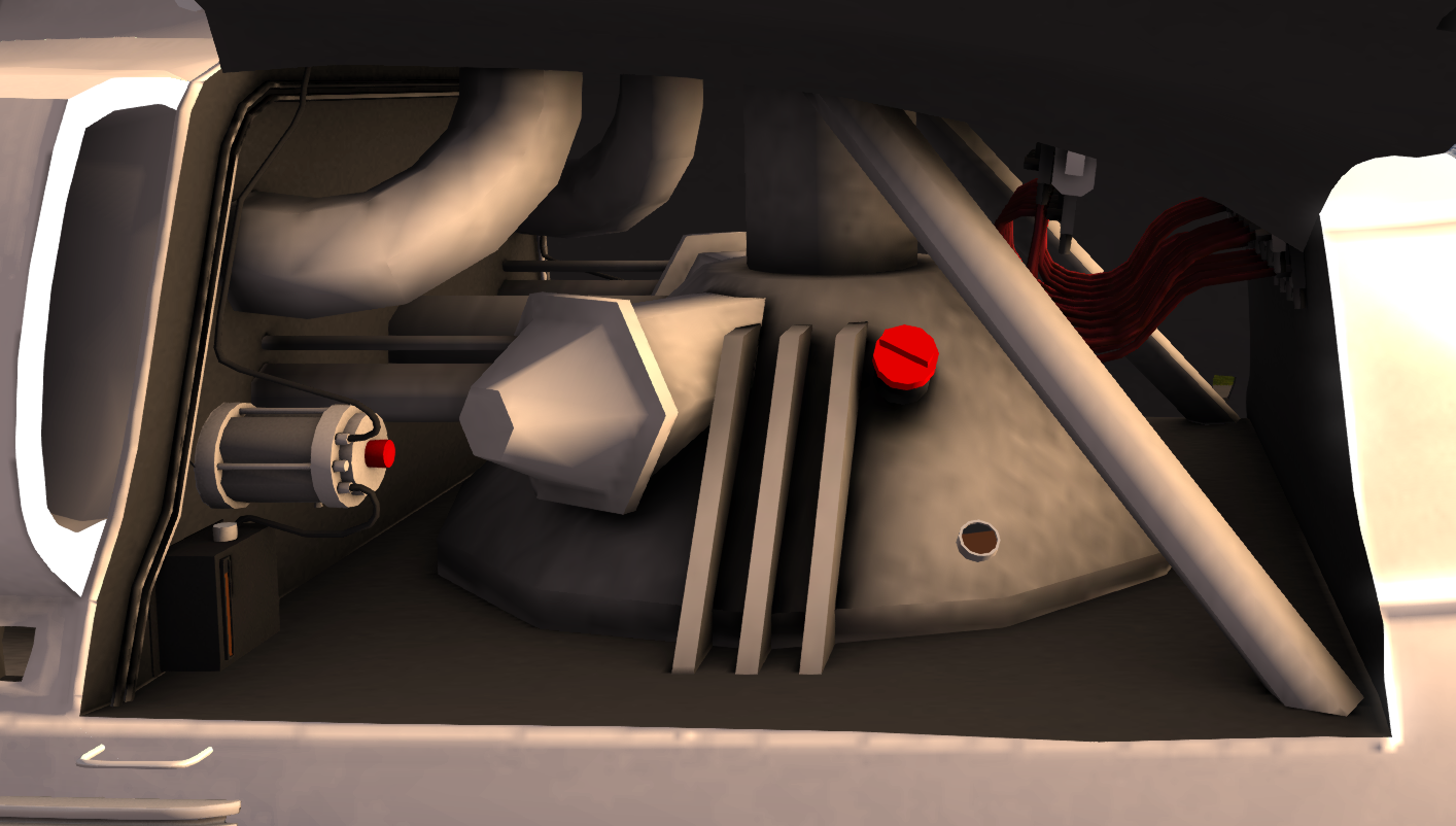
| − | The main transmission (see ) is located directly below the main rotors. It can be accessed through panels on either side of the aircraft. Click on the transmission to check its status, or repair it if it is damaged. The filler cap for the main transmission is located on the right side. Click the red cap to add one quart of transmission fluid. The reservoir takes a total of 8 quarts with the level visible through a sightglass near the base of the transmission. | + | The main transmission (see <xr id="fig:xmshnMain"/>) is located directly below the main rotors. It can be accessed through panels on either side of the aircraft. Click on the transmission to check its status, or repair it if it is damaged. The filler cap for the main transmission is located on the right side. Click the red cap to add one quart of transmission fluid. The reservoir takes a total of 8 quarts with the level visible through a sightglass near the base of the transmission. |
====Tail Rotor Gearbox==== | ====Tail Rotor Gearbox==== | ||
| − | The tail rotor gearbox can be accessed by opening the panel on the tail rotor hub (see ). Click on the gearbox to check for damage or repair if necessary. A red filler cap can be clicked to add an additional quart of transmission fluid up to the total capacity of 3 quarts. The slightglass on the bottom can be used to check the current level. | + | The tail rotor gearbox can be accessed by opening the panel on the tail rotor hub (see <xr id="fig:xmshnTail"/>). Click on the gearbox to check for damage or repair if necessary. A red filler cap can be clicked to add an additional quart of transmission fluid up to the total capacity of 3 quarts. The slightglass on the bottom can be used to check the current level. |
| + | |||
| + | ===HYDRAULIC SYSTEMS=== | ||
| − | + | The H-160 has two hydraulic systems (see <xr id="fig:hydraulic"/>) with pumps located on either side of the main transmission. They are accessed through the transmission panels on either side of the helicopter. The #1 system is on the left side while the #2 system is on the right. Clicking on a pump checks for damage and repairs any damage if present. The hydraulic fluid is contained in a reservoir next to each pump. Click the filler cap on top to add a quart of fluid up to the 3 quart capacity. A slightglass on the front shows the current fluid level. | |
| − | The H-160 has two hydraulic systems (see ) with pumps located on either side of the main transmission. They are accessed through the transmission panels on either side of the helicopter. The #1 system is on the left side while the #2 system is on the right. Clicking on a pump checks for damage and repairs any damage if present. The hydraulic fluid is contained in a reservoir next to each pump. Click the filler cap on top to add a quart of fluid up to the 3 quart capacity. A slightglass on the front shows the current fluid level. | ||
===ELECTRICAL SYSTEMS=== | ===ELECTRICAL SYSTEMS=== | ||
| − | ====Generators | + | ====Generators==== |
| − | The #1 and #2 generators (see ) are mounted on the sides of the main transmission. They are accessed through the panels for the main transmission. Click a generator to check for damage or repair any existing damage. | + | The #1 and #2 generators (see <xr id="fig:generator"/>) are mounted on the sides of the main transmission. They are accessed through the panels for the main transmission. Click a generator to check for damage or repair any existing damage. |
====DC Buses==== | ====DC Buses==== | ||
| − | The DC Buses can be examined by clicking on the breaker panel located near the floor of the aircraft on the pilot side. Clicking will check for DC bus shorts, and repair the shorts if they are detected. | + | The DC Buses can be examined by clicking on the breaker panel (see <xr id="fig:breakerPanel"/>) located near the floor of the aircraft on the pilot side. Clicking will check for DC bus shorts, and repair the shorts if they are detected. |
===AVIONICS=== | ===AVIONICS=== | ||
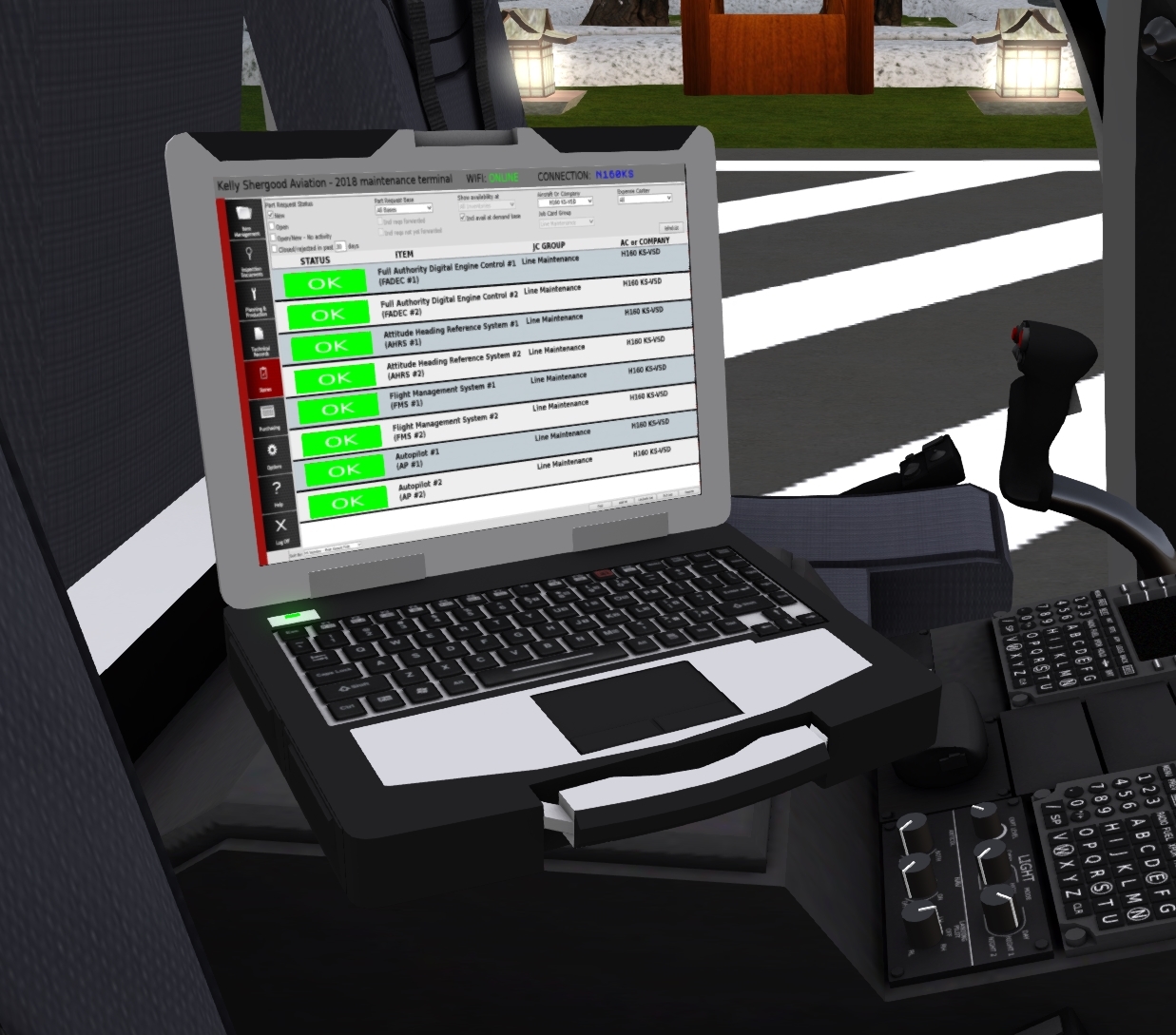
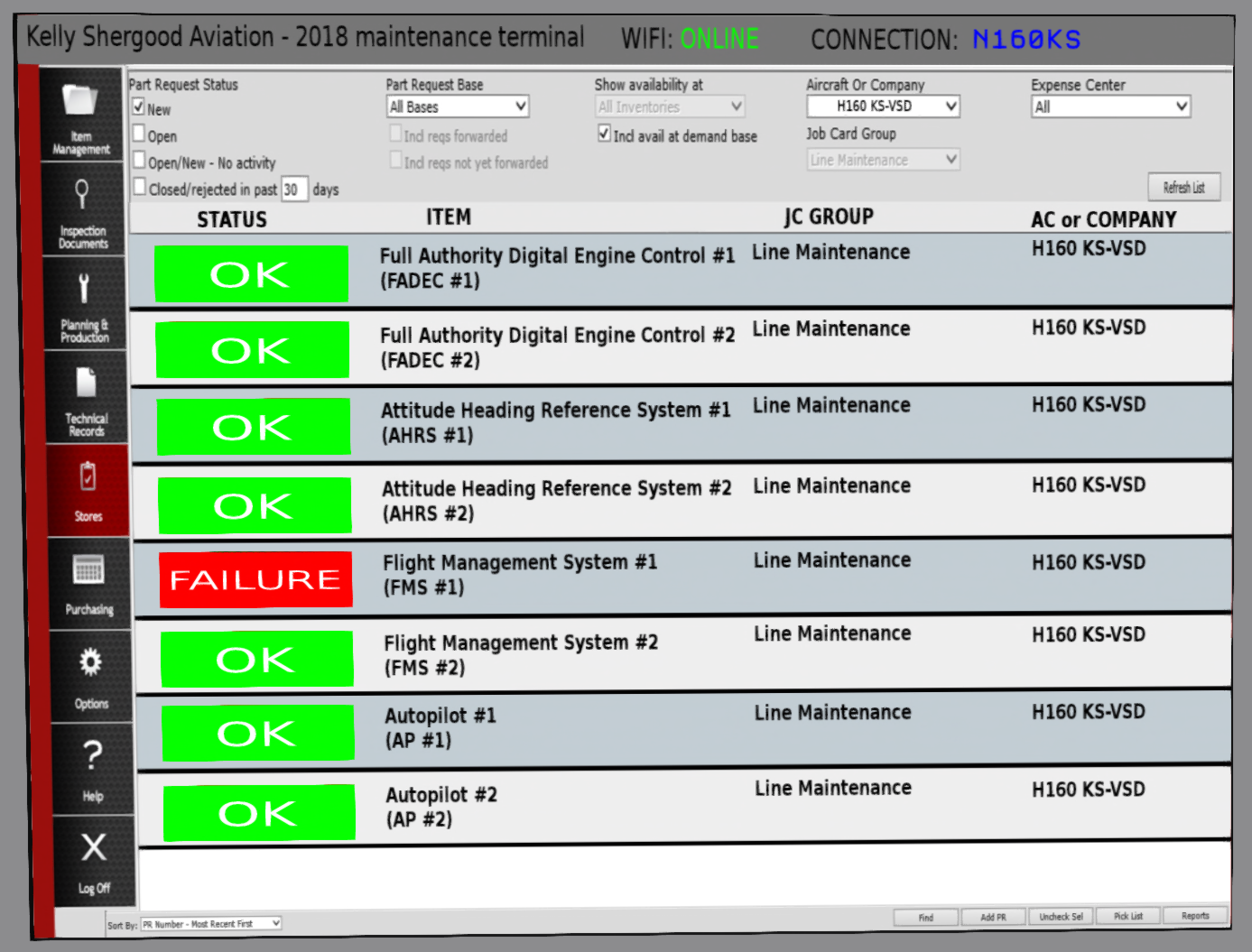
| − | Problems with the H-160 avionics may be diagnosed and repaired using the avionics analyzer. You can get the analyzer through the aircraft menu system by selecting "Analyzer" from the "@Get" submenu. To use the analyzer, rez it in or near the aircraft up to 10m from the aircraft (see | + | Problems with the H-160 avionics may be diagnosed and repaired using the avionics analyzer. You can get the analyzer through the aircraft menu system by selecting "Analyzer" from the "@Get" submenu. To use the analyzer, rez it in or near the aircraft up to 10m from the aircraft (see <xr id="fig:avionicsAnalyzer"/>). The analyzer will communicate with the aircraft over a wifi connection. Verify that it is connected to the correct aircraft by checking the upper right portion of the screen (see <xr id="fig:analysis"/>). Make sure the tail number displayed there matches the tail number of the aircraft you are diagnosing. |
The screen will show a list of the replaceable avionics components. A green "OK" will be shown if the unit is working properly, or a red "FAILURE" will be shown if a fault is detected in a unit. You can also click on a unit name to rerun a test on that unit. If a device is failed, click on that line to send a request to the manufacturer for a replacement, and install the new unit. | The screen will show a list of the replaceable avionics components. A green "OK" will be shown if the unit is working properly, or a red "FAILURE" will be shown if a fault is detected in a unit. You can also click on a unit name to rerun a test on that unit. If a device is failed, click on that line to send a request to the manufacturer for a replacement, and install the new unit. | ||
Latest revision as of 16:46, 23 October 2021
SECTION 8. AIRCRAFT SERVICING
Contents
1 GENERAL
This section describes all servicing and repair procedures for the H-160.
2 REFUELING
The fuel supply system on the H160 consists of a single 276 gallon tank with a baffle at the bottom creating two 32 gallon partitions, one for each engine. The baffles ensure that at least 32 gallons is reserved for each engine. The system is entirely gravity fed. No pumps are required to move fuel from the main upper portion of the tank to the lower engine-specific portion. The fuel cap is located on the left side of the aircraft behind the passenger compartment (see Figure 1). Either KellyFuel or DSA fuel systems may be used. The fuel cap must be removed to allow the fuel system to be used. Click the cap to remove or replace it.
3 EXTERNAL POWER
An External Power Unit (EPU) Port is located above and to the left of the fuel cap (see Figure 1). A small door protects the port. The port is compatible with the SA Ground Power Unit.
4 COVER AND CHOCKS
When parking your aircraft for an extended period of time, it is recommended that you use the provided covers and chocks (see Figure 2). The covers may be applied by selecting the "Covers" option from the @Get submenu. Click the covers again to remove (derez) them. Only the owner is allowed to remove the covers this way. Covers will also automatically derez if the aircraft moves more than 0.01m from its resting position. Alternatively, it is possible to take the covers to inventory then rez them near your aircraft. They will automatically snap into the proper position. You may only apply covers to your own aircraft this way.
5 ENGINES
The engines (see Figure 3) are located on either side below and just aft of the main rotor transmission. The engine on left side when looking forward is the #1 engine, and the engine on the right side is the #2 engine. Each engine has a cowling that can be opened for access to the internals. Click on an engine to check for damage, or repair any existing damage. Each engine has an 8 quart oil reservoir. Engines should not be operated with less than 6 quarts. The oil level can be checked with a sightglass below the filler. Click on the red cap to add a quart of oil to an engine.
6 TRANSMISSION
6.1 Main Transmission
The main transmission (see Figure 4) is located directly below the main rotors. It can be accessed through panels on either side of the aircraft. Click on the transmission to check its status, or repair it if it is damaged. The filler cap for the main transmission is located on the right side. Click the red cap to add one quart of transmission fluid. The reservoir takes a total of 8 quarts with the level visible through a sightglass near the base of the transmission.
6.2 Tail Rotor Gearbox
The tail rotor gearbox can be accessed by opening the panel on the tail rotor hub (see Figure 5). Click on the gearbox to check for damage or repair if necessary. A red filler cap can be clicked to add an additional quart of transmission fluid up to the total capacity of 3 quarts. The slightglass on the bottom can be used to check the current level.
7 HYDRAULIC SYSTEMS
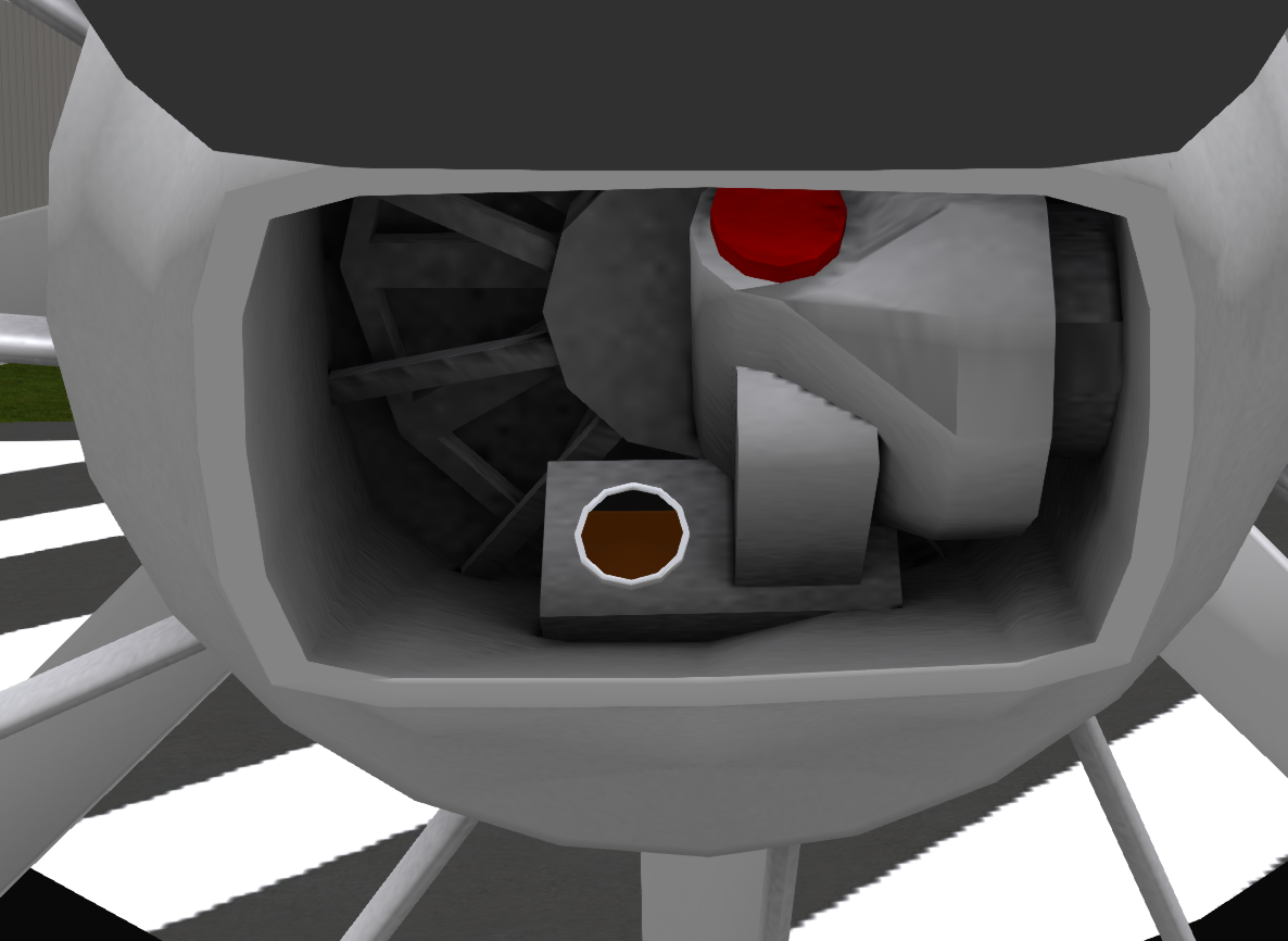
The H-160 has two hydraulic systems (see Figure 6) with pumps located on either side of the main transmission. They are accessed through the transmission panels on either side of the helicopter. The #1 system is on the left side while the #2 system is on the right. Clicking on a pump checks for damage and repairs any damage if present. The hydraulic fluid is contained in a reservoir next to each pump. Click the filler cap on top to add a quart of fluid up to the 3 quart capacity. A slightglass on the front shows the current fluid level.
8 ELECTRICAL SYSTEMS
8.1 Generators
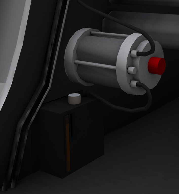
The #1 and #2 generators (see Figure 7) are mounted on the sides of the main transmission. They are accessed through the panels for the main transmission. Click a generator to check for damage or repair any existing damage.
8.2 DC Buses
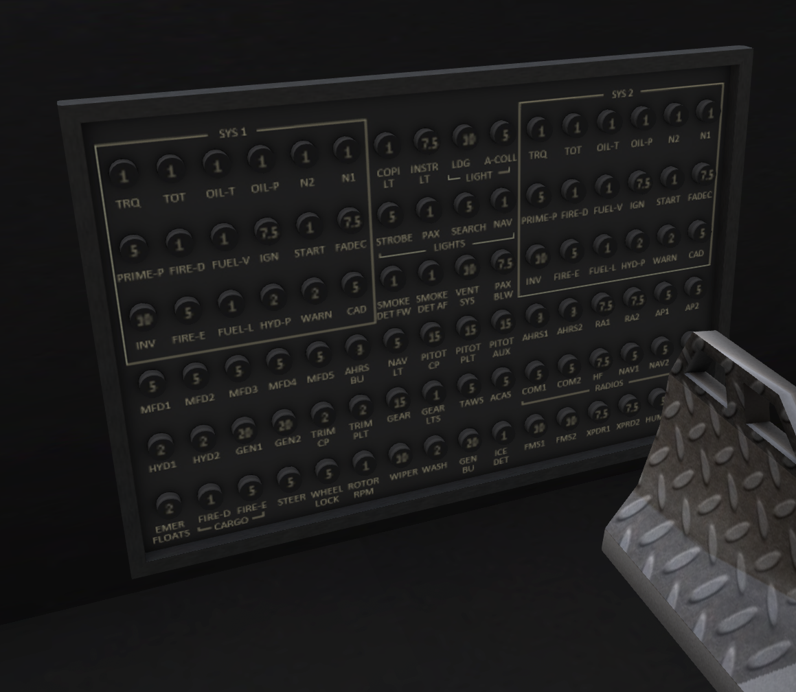
The DC Buses can be examined by clicking on the breaker panel (see Figure 8) located near the floor of the aircraft on the pilot side. Clicking will check for DC bus shorts, and repair the shorts if they are detected.
9 AVIONICS
Problems with the H-160 avionics may be diagnosed and repaired using the avionics analyzer. You can get the analyzer through the aircraft menu system by selecting "Analyzer" from the "@Get" submenu. To use the analyzer, rez it in or near the aircraft up to 10m from the aircraft (see Figure 9). The analyzer will communicate with the aircraft over a wifi connection. Verify that it is connected to the correct aircraft by checking the upper right portion of the screen (see Figure 10). Make sure the tail number displayed there matches the tail number of the aircraft you are diagnosing.
The screen will show a list of the replaceable avionics components. A green "OK" will be shown if the unit is working properly, or a red "FAILURE" will be shown if a fault is detected in a unit. You can also click on a unit name to rerun a test on that unit. If a device is failed, click on that line to send a request to the manufacturer for a replacement, and install the new unit.
