Difference between revisions of "Chinook CH-47/Systems"
(→Power Train System) |
(→Power Train System) |
||
| (15 intermediate revisions by the same user not shown) | |||
| Line 331: | Line 331: | ||
]] | ]] | ||
| | | | ||
| − | [[File:Ch47-xmshnTemp.png|thumb| | + | [[File:Ch47-xmshnTemp.png|thumb|150px| |
<figure id="fig:xmshnTemp"><caption>Trans. Temp.</caption></figure> | <figure id="fig:xmshnTemp"><caption>Trans. Temp.</caption></figure> | ||
]] | ]] | ||
| Line 341: | Line 341: | ||
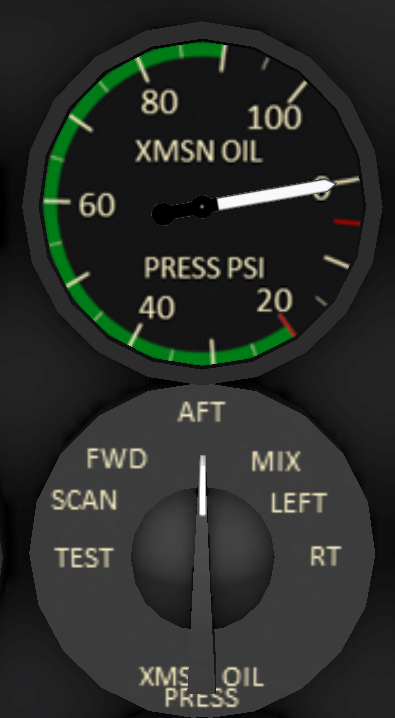
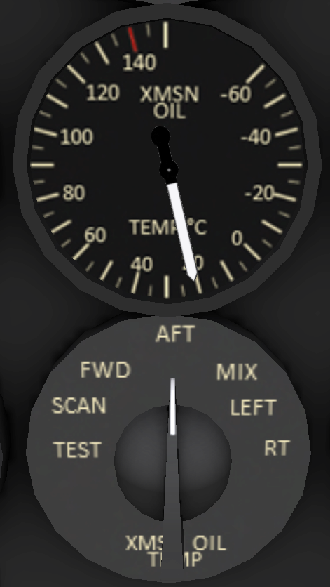
The transmission can be monitored from the cockpit through pressure and temperature gauges as well as alert lights indicating when tolerances are exceeded. shows the pressure and temperature gauges for the transmission. Below each gauge is a selector to indicate which system to display. In addition to the single system settings there is a SCAN position that displays the highest system temperature on temperature gauge, and the lower pressure on the pressure gauge. | The transmission can be monitored from the cockpit through pressure and temperature gauges as well as alert lights indicating when tolerances are exceeded. shows the pressure and temperature gauges for the transmission. Below each gauge is a selector to indicate which system to display. In addition to the single system settings there is a SCAN position that displays the highest system temperature on temperature gauge, and the lower pressure on the pressure gauge. | ||
| + | |||
| + | <br clear=all> | ||
=== Rotor System === | === Rotor System === | ||
| + | |||
| + | Lift is produced by two fully articulated counter-rotating rotors. Each rotor has three blades and is driven through a transmission. The rotor RPM is displayed on pilot and co-pilot side tachometers (see <xr id="fig:pilotPanel" />, Item 16). The tachometers include an inner needle that displays percent RPM from 0-60, and an outer needle that displays RPM above 60%. | ||
| + | |||
=== Electric System === | === Electric System === | ||
| + | |||
| + | ==== Overview ==== | ||
| + | |||
| + | [[File:Ch47-electrical.png|800px]] | ||
| + | <figure id="fig:electrical"><caption>Electrical System</caption></figure> | ||
| + | |||
| + | |||
| + | The Chinook electrical system (see <xr id="fig:electrical" />) consists of two AC buses and two DC buses. The AC buses are powered by two primary generators or by an APU generator which produce 115V at 400 Hz. The DC system operates at 28 volts which is powered through rectifiers from each AC bus, or from a 24-volt nickel-cadmium battery. | ||
| + | |||
| + | The AC buses are connected by two AC bus ties. The bus ties are controlled by gang bar switches located near the bottom of the Power Distribution Panels (PDP) located behind and to side of the pilot and copilot seats. The #1 PDP is located near the co-pilot seat, while the #2 PDP is located near the pilot seat. | ||
| + | |||
| + | A hot battery bus supplies power to several devices even when the BATT switch is OFF. These devices include the digital clock, the APU control circuit, and the fluid level check for the maintenance panel. | ||
| + | |||
| + | [[File:Ch47-elecPanel.png|thumb|right| | ||
| + | <figure id="fig:elecPanel"><caption>Electrical Panel</caption></figure> | ||
| + | ]] | ||
| + | |||
| + | ==== Electrical Panel ==== | ||
| + | |||
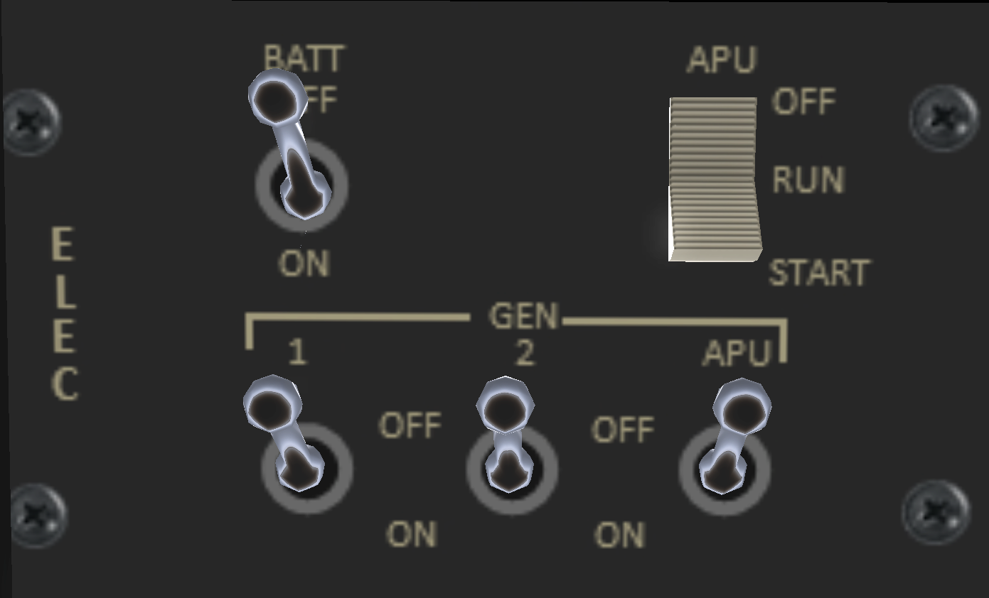
| + | The electrical system is controlled through the electrical panel (see ) located on the co-pilot side of the overhead panel. The electrical panel includes the following switches: | ||
| + | * BATT - When in the ON position, energizes the DC bus from the main battery. | ||
| + | * APU - Three position switch with OFF, RUN and START positions. The START position is spring loaded to the RUN position. The APU is started by holding the switch in the RUN position for 2-3 seconds, then releasing. It may be necessary to click once to move from OFF to RUN, then again to hold in the START position. | ||
| + | * GEN 1 - Supplies AC power to the #1 AC bus. The generator is powered off the aft transmission and is powered when the rotor RPM is above 70%. | ||
| + | * GEN 2 - Supplies AC power to the #2 AC bus. The generator is powered off the aft transmission and is powered when the rotor RPM is above 70%. | ||
| + | * APU GEN - Supplies AC power to the #1 AC bus when the APU is running. | ||
| + | |||
=== Utility Systems === | === Utility Systems === | ||
| + | |||
| + | |||
| + | ==== Anti-Ice ==== | ||
| + | Anti-icing is provided for the pitot tubes and the windshield. An anti-ice panel is located on the overhead panel with individual switches for each of the systems. Heat for the windshield anti-ice is provided through a conductive film between layers. | ||
| + | |||
| + | [[File:Ch47-heating.png|thumb|right| | ||
| + | <figure id="fig:heating"><caption>Cabin Heat</caption></figure> | ||
| + | ]] | ||
| + | |||
| + | ==== Cabin Heat ==== | ||
| + | |||
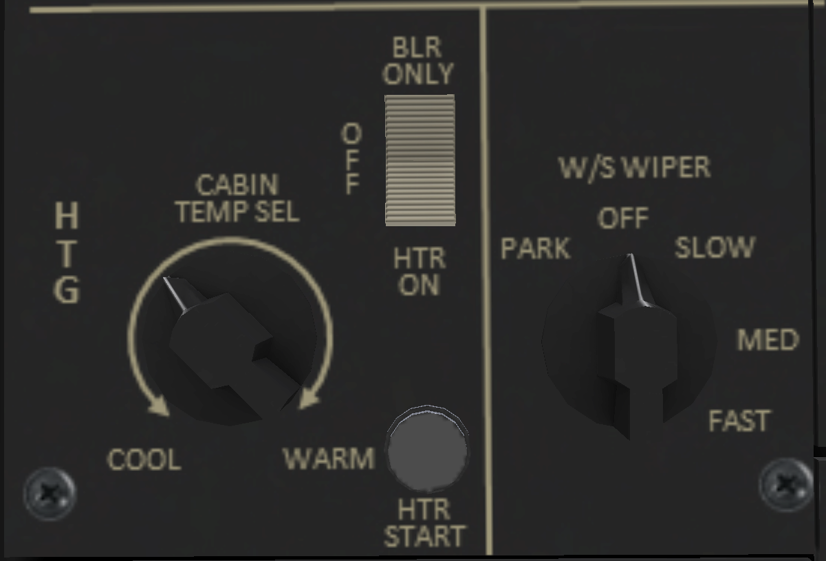
| + | The cabin heat panel is located on the overhead panel on the copilot side. The panel consists of a temperature select knob, a three position mode switch, and a start button for the heater. The mode switch has position BLR ONLY for only the blower, and OFF position, and a HTR position for the heater. To use the heater place the mode switch in the HTR position, then press the HTR START button to start the heater. For SL purposes, the heater is primarily for RP, but does include blower sounds. | ||
| + | |||
| + | ==== Windshield Wipers ==== | ||
| + | |||
| + | Windshield wiper controls are located to the right of the heater controls. It consists of single 5-position rotary switch. The wiper controls are for RP only in SL. | ||
| + | |||
| + | ==== Maintenance Panel ==== | ||
| + | |||
| + | The maintenance panel is on the right side of the aircraft above the ramp. The maintenance panel is used to help diagnose system malfunctions and should be periodically monitored during flight by the flight engineer. For details on the maintenance panel, see [[Chinook CH-47/Servicing|SECTION 9 - Servicing, Section 3.]] | ||
| + | |||
=== Lighting === | === Lighting === | ||
| + | |||
| + | [[File:Ch47-ltgExt.png|thumb|right| | ||
| + | <figure id="fig:ltgExt"><caption>External Lighting</caption></figure> | ||
| + | ]] | ||
| + | [[File:Ch47-ltgPlt.png|thumb|right| | ||
| + | <figure id="fig:ltgPlt"><caption>Pilot Lighting</caption></figure> | ||
| + | ]] | ||
| + | [[File:Ch47-ltgCpl.png|thumb|right| | ||
| + | <figure id="fig:ltgCpl"><caption>Co-Pilot Lighting</caption></figure> | ||
| + | ]] | ||
| + | [[File:Ch47-ltgAux.png|thumb|right| | ||
| + | <figure id="fig:ltgAux"><caption>Auxiliary Lighting</caption></figure> | ||
| + | ]] | ||
| + | [[File:Ch47-ltgInt.png|thumb|right| | ||
| + | <figure id="fig:ltgInt"><caption>Internal Lighting</caption></figure> | ||
| + | ]] | ||
| + | |||
| + | ==== External Lighting ==== | ||
| + | The external lighting panel (see <xr id="fig:ltgExt" />) includes the following switches: | ||
| + | *ANTI COL - Two separate switch control the top and bottom anti-collision lights. The anit-collision lights flash red and should normally be on any time the rotors are turning, or are about to start turning. | ||
| + | *POSN - Controls the position lights. The position lights consist of a red light on the left sponson, a blue/green light on the right sponson, and a white light on the aft side of the aft pylon. Position lights should be used between sunset and sunrise, as well as during a total solar eclipse. | ||
| + | *FORM - A six position knob controlling the intensity of the formation lights with an OFF position, and 5 intensity levels. Formation lights are for use at night when flying in multi-aircraft formations to improve visibility and aid in identification of the aircraft. There are two type of formation lights: normal and NVG (Night-Vision Goggles). | ||
| + | *NORM/NVG - Selects which set of formation lights should be used. When NORM is selected, the normal rectangular-shaped formation lights are used. When NVG is selected, the round night-vision formation lights are used. | ||
| + | |||
| + | |||
| + | ==== Pilot Lighting ==== | ||
| + | The pilot lighting panel (see <xr id="fig:ltgPlt" />) is located on the pilot side of the overhead panel. It includes the following switches: | ||
| + | *PLTSRCHLT - Pilot side Search (Landing) Light | ||
| + | *CTR INST - Selectable intensity center instrument lights. | ||
| + | *PLT INST - Selectable intensity pilot instrument lights. | ||
| + | |||
| + | ==== Co-Pilot Lighting ==== | ||
| + | The copilot lighting panel (see <xr id="fig:ltgCpl" />) is located on the pilot side of the overhead panel. It includes the following switches: | ||
| + | *CPLTSRCHLT - Co-Pilot side Search (Landing) Light | ||
| + | *CPLT INST - Selectable intensity copilot instrument lights. | ||
| + | *OVHD CSL - Selectable intensity overhead console lights. | ||
| + | |||
| + | ==== Auxiliary Lighting ==== | ||
| + | An auxiliary light panel is located at the top center of the overhead panel (see <xr id="fig:ltgAux" />). The panel contains two rotary switches. The left switch controls the light intensity of the center panel between the pilot and copilot seats. The right position is for the optional stick position indicator (not installed in this aircraft). | ||
| + | |||
| + | ==== Internal Lighting ==== | ||
| + | The internal lighting panel (see <xr id="fig:ltgInt" />) is located on the pilot side of the overhead panel. It includes the following switches: | ||
| + | *INST - Instrument flood lights are located under the instrument sun visor. Brightness is controlled by the near by knob with an OFF position, and multiple brightness levels from *DIM to OFF. Instrument flood lights will illuminate only if this switch is ON and the brightness knob is at a setting other than OFF. | ||
| + | *OVHD - Over flood lights are located on the bulkhead behind the pilot and copilot seats. Brightness is controlled by the near by knob with an OFF position, and multiple brightness levels from DIM to OFF. The overhead flood lights will illuminate only if this switch is ON and the brightness knob is at a setting other than OFF. | ||
| + | *EMER EXIT - Arms or disarms the emergency exit lights. These are described in the next section. | ||
| + | *DOME - Turns on the overhead dome lights over and slightly behind the pilot and copilot seats. | ||
| + | |||
| + | <br clear=all> | ||
=== Master Alert/Caution Panel === | === Master Alert/Caution Panel === | ||
| + | |||
| + | [[File:Ch47-alertPanel.png|thumb|right| | ||
| + | <figure id="fig:alertPanel"><caption>Alert/Caution Panel</caption></figure> | ||
| + | ]] | ||
| + | |||
| + | |||
| + | An alert and caution light panel is located on the center console. The panel consists of 4 columns of 16 lights. The upper 12 rows indicate abnormal conditions, while the bottom four (colored green) indicated advisory conditions. Each alert light indicates a malfunctioning or non-operative system. While it is normal for some alert lights to be illuminated before engine start, in general all alert lights should be off before attempting flight, and precautionary landing should be considered when any lights indicate while in flight. A complete list of the lights and their meaning are given in [[Chinook_CH-47/Appendices#CAUTION.2FADVISORY_PANEL_LIGHTS|Appendex - Advisory Panel]]. | ||
| + | |||
| + | Two master caution lights on the pilot and copilot sides illuminate when any of the alert lights other than the green advisory lights illuminate. The master caution light can be dismissed by pressing it. When dismissed, the master caution light will come on again if any new alert lights illuminate. | ||
Latest revision as of 00:02, 23 October 2021
SECTION 2. SYSTEMS
Contents
1 Helicopter
1.1 General
The Shergood CH-47D is a twin-turbine engine tandem rotor helicopter designed for transportation of cargo, troops and weapons during day, night, visual and instrument conditions. The heicopter is powered by two T550GA-714A shaft-turbine engines on the aft fuselage. Each engine drives a separate engine transmission. Drive shafts from each engine transmission is connected to a shared combining transmission which in turn drives the forward and aft transmissions. The forward transmission is housed in the forward pylon above the cockpit, the combining transmission is housed on the forward side of the aft pylon, and the aft transmission is also housed in the aft pylon behind the combining transmission. When the rotors are not turning, and APU (Auxilary Power Unit) can be used to supply electrical power and hydraulic pressure. Fuel is carried in pods on the sides with main, forward auxilary and aft auxilary tanks on each side. An entrance door is located on the forward right side of the main cabin, while a hydraulically powered ramp is in the back.
1.2 Gross Weight
The maximum gross weight is 50,000 pounds.
1.3 Landing Gear Systems
The landing gear system consists for four non-retractable landing gears mounted on the fuselage pods. The forward gear a fixed with twin wheels. The aft landing gears are single wheels mounted on swivels. In addition, the aft right gear can be steered from the cockput to improve ground handling. Landing Gear Proximity Switches Proximity switches are mounted on each aft landing gear. GROUND CONTACT lights on the maintenance panel in the aft rear of the helicopter indicate when the switches have been activated. While ground contact switches are activated, the trim system will position the forward and aft rotors on GND position for better ground handling.
1.4 Steering and Swivel Lock System
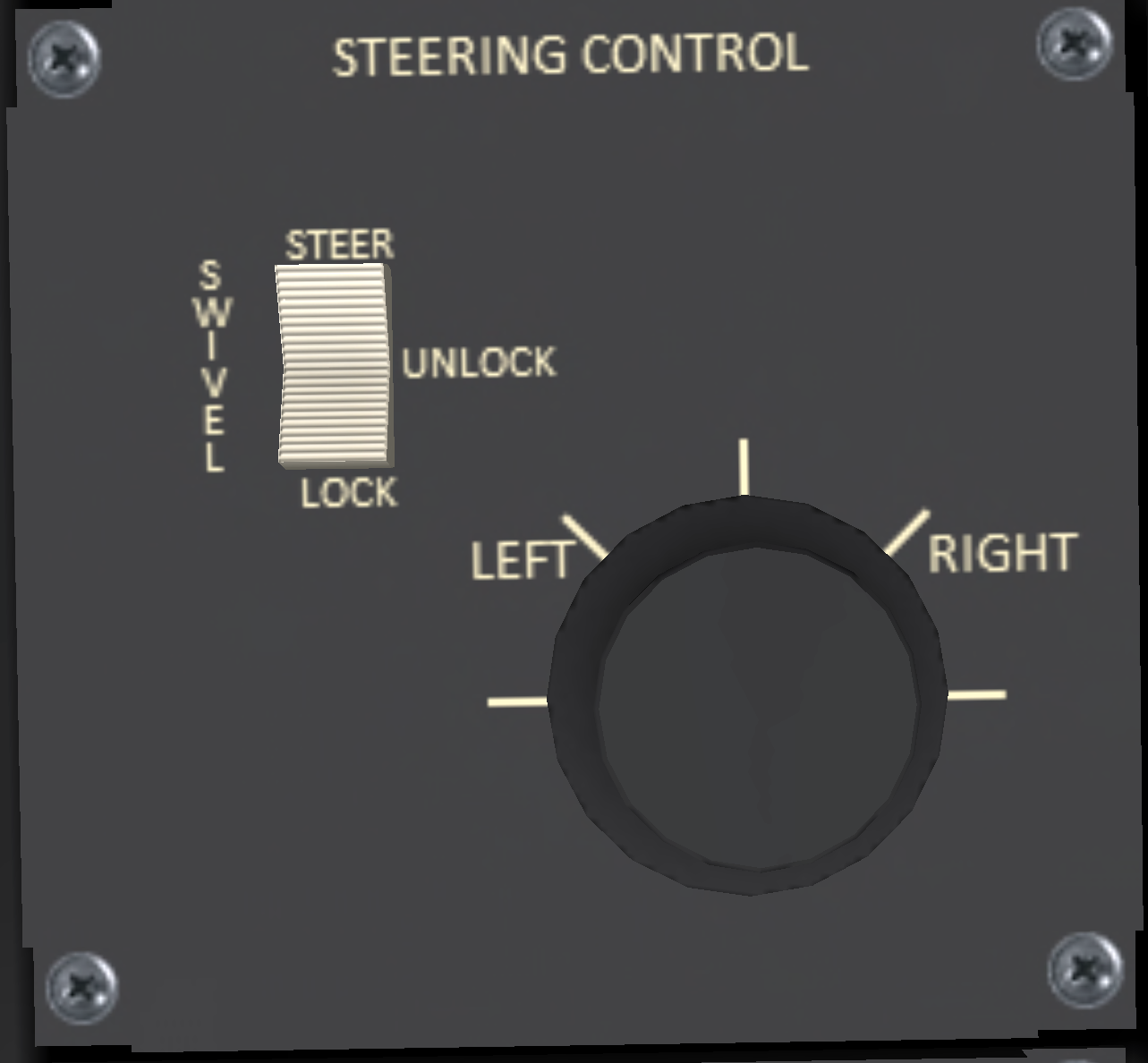
The ground steering control panel (see Figure 1) is located on the center panel between the pilot and co-pilot seats. The ground steering mode is controlled by a three position switch with the following positions:
- STEER - Active steering of the right rear wheel.
- UNLOCK - Free castering of the rear wheels.
- LOCK - Rear wheels locked in straight forward position.
The steering system is powered by the utility hydraulic system. In addition the PWR STEER switch on the upper console must also be in the ON position to use ground steering, or change the active steering mode. When the STEER steering mode is selected, the "keyboard" control mode is active, and the helicopter is in ground contact, the left/right arrow keys that normally control lateral cyclic will switch to controling the wheel position displayed as pedal inputs.
1.5 Parking Brake
A parking brake is located below the lower left corner of the pilot-side instrument panel. Click the parking brake to pull or push the handle. A green "PARK BRAKE ON" capsule will illuminate to indicate the parking brake is engaged. The parking brake requires hydraulic pressure from the utility system, and for the PWR STEER switch to be in the ON position to activate or deactivate. If there is no hydraulic pressure, the parking brake handle can still be pulled or pushed, but the brakes will not engage.
1.6 Pilot-Side Instrument Panel
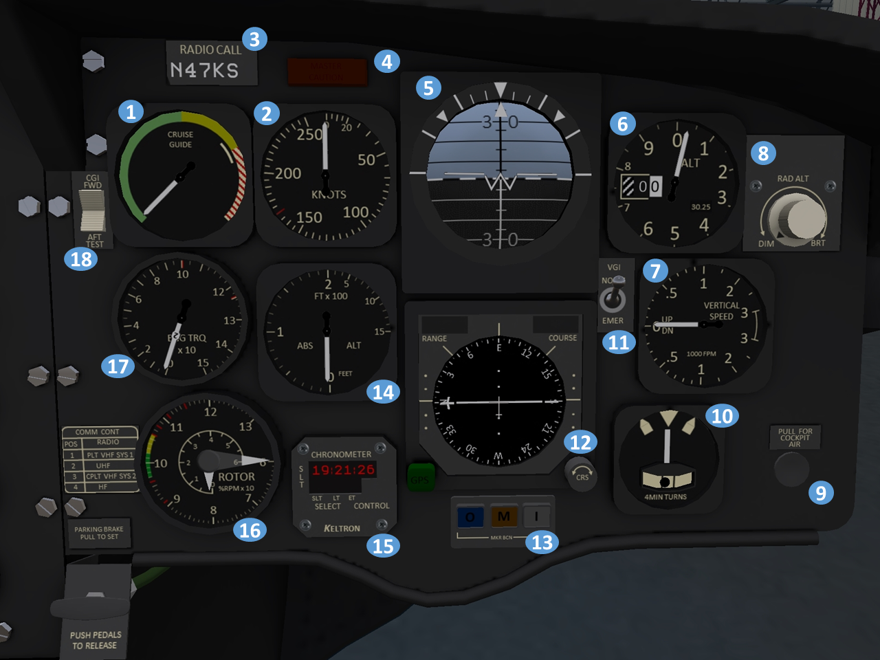
| 1. Cruise Guide Indicator (CGI) | 2. Airspeed Indicator | 3. Radio Call Sign Plate | 4. Master Caution Light |
| 5. Attitude Indicator | 6. Altimeter | 7. Vertical Speed Indicator (VSI) | 8. Radar Altimeter Dimmer Knob |
| 9. Cockpit Air Knob (display only) | 10. Turn and slip indicator | 11. VGI (Vertical Gyro Indicator) mode switch | 12. Horizontal Situation Indicator (HSI) |
| 13. Marker Beacon Lights | 14. Radar Altimeter | 15. Chronometer | 16. Rotor tachometer (RPM) |
| 17. Torquemeter | 18. CGI (Cruise Guide Indicator) test switch |
1.7 Co-Pilot-Side Instrument Panel
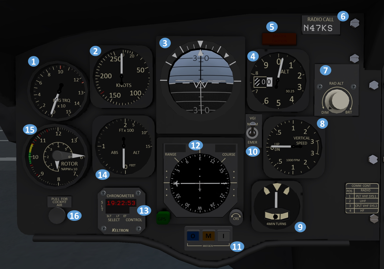
| 1. Torquemeter | 2. Airspeed Indicator | 3. Attitude Indicator | 4. Altimeter |
| 5. Master Caution Light | 6. Radio Call Sign Plate | 7. Radar Altimeter Dimmer Knob | 8. Vertical Speed Indicator (VSI) |
| 9. Turn and slip indicator | 10. VGI (Vertical Gyro Indicator) mode switch | 11. Horizontal Situation Indicator (HSI) | 12. Chronometer |
| 13. Radar Altimeter | 14. Cockpit Air Knob (display only) | 15. Rotor tachometer (RPM) |
1.8 Center Instrument Panel
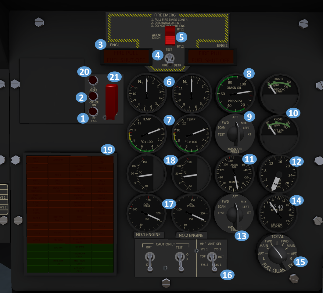
| 1. IFF Failed Indicator Light | 2. Transponder Cypher Active Indicator Light | 3. FIRE PULL handles (Fuel Shut-Off) | 4. Fire Detection Test Switch |
| 5. Agent Discharge Switch | 6. Gas Producer (N1) Tachometer | 7. Power Turbine Inlet Temp. (PTIT) Indicator | 8. Transmission Oil Pressure Indicator |
| 9. Transmission Oil Pressure Selector | 10. Longitudinal Cyclic Trim Indicators | 11. Transmission oil temperature indicator | 12. Fuel flow indicator |
| 13. Transmission oil temperature selector | 14. Fuel quantity indicator | 15. Fuel quantity selector | 16. Caution light and antenna selector |
| 17. Engine Oil Pressure Indicators | 18. Engine Oil Temperator Indicators | 19. Caution/Advisory Panel | 20. GPS Alert Indicator |
| 21. GPS Zeroize Switch |
2 Emergency Equipment
2.1 Engine Fire Detection System
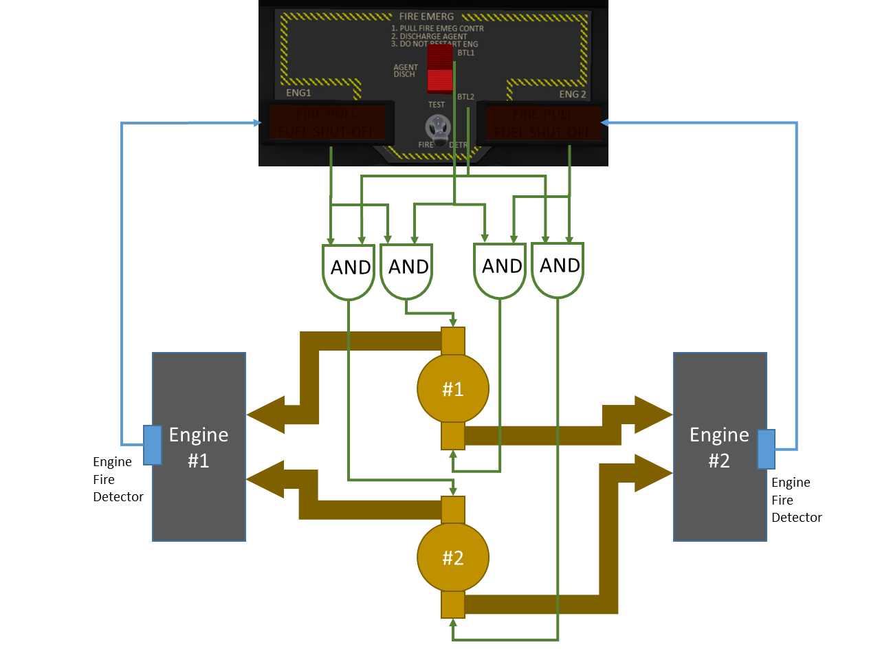
The engine fire detection/extinguisher system is designed to extinguish fires in the engine compartment only. The system (see Figure 5) is comprised of two FIRE PULL handles, indicator lights on each handle, an agent discharge switch, a FIRE DETR test switch, and two fire extinguisher agent containers. When a fire is detected in an engine, a light reading "FIRE PULL FUEL SHUT-OFF" will illuminate on the handle for the affected engine. To discharge agent into an engine, first pull the handle to select the engine, then move the AGENT DISCH rocker switch to select a bottle to be discharged. Power is supplied to the fire detection and #1 and #2 extinguisher systems through the #1 and #2 DC buses, respectively.
To perform a system test and check the warning lights, the FIRE DETR switch can be placed in the TEST position. If the system is functioning properly, the "FIRE PULL" indication on both handles will illuminate.
2.2 TROOP WARN Panel
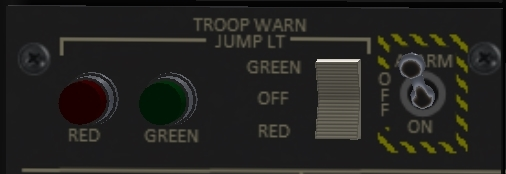
Two troop alarm and jump light boxes are mounted in the rear of the aircraft. The forward box is mounted near the ceiling to the left of the cockpit entrance. The aft box is mounted to the right side of the ramp in the rear of the aircraft. Each box is comprised of an electrical bell and a red and green light fixture on either side. The troop alarm system is controlled through a panel on the overhead switch panel (see Figure 6). A three position switch controls which light is illuminated, and a switch turns the bell on or off. Indicator lights on the panel indicate when either light is illuminated.
The troop warning panel can service multiple purposes. It can be used to warn troops to keep clear of APU during engine start, to indicate emergency situations with predetermined signals, or to indicate when the aircraft is over a drop zone.
3 Engines and Related Systems
3.1 General
The Shergood CH-47D is equipped with two T55-GA-714A engines mounted in separate nacelles on either side of the aft pylon. Each engine is capable of producing up to 4,867 shaft horse power. The compressor is comprised of 7 axial stages and one centrifugal stage. Hot gasses leaving the combustor power a two stage turbine driving the compressor and a two stage power output turbine. The engine is kept lubricated by a 12 quart oil tank located at the inlet side of the engine. Floats in the oil reservoir activate the low oil caution lights when the oil is below minimum capacity.
3.2 Engine Condition Levers
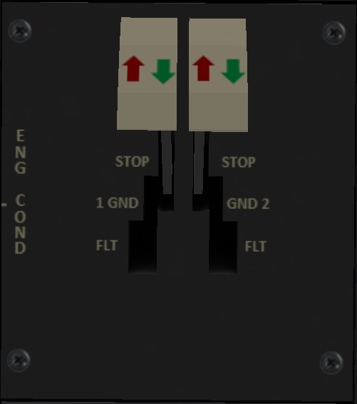
The engine condition levers (ECL) are located in the overhead switch panel (see Figure 7). Each ECL has OFF, ground (GND) and flight(FLT) positions. ECLs should be in the GND position for engine start, and set to the OFF position to shut down the engine.
3.3 FADEC Description
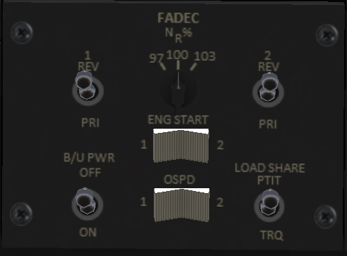
The CH-47D engines are controlled by dual FADEC (Fully Authority Digital Engine Control) units, one for each engine. The FADEC oversees engine start and maintains proper operating RPM during flight. The control panel for the FADECs is located on the upper switch panel and is shown shown in Figure 8. The FADEC for each engine can be operated in primary (PRI) or revisionary (REV) mode. Two switches control the mode the respective FADEC. In normal operation, primary mode should be used. Reversionary mode can be used in the event of failure of the primary system. Engine RPM will not be as stable using revisionary mode.
An Nr selector can be used to select the target rotor RPM between 97% and 103%. In normal use, 100% should be selected. The 97% setting can be used during water operations to reduce spray.
The FADEC units are normally powered with dedicated alternators on each engine. The backup power switch (labeled B/U POWER) when ON enables the FADEC units to be powered from the aircraft battery bus as well. The B/U POWER switch should always be ON during engine operation.
The LOAD SHARE switch selects between PTIT (turbine inlet temperature) and torque matching for sharing load between engines. Torque matching is normally the preferred option. Load sharing may not be as accurate in PTIT mode.
The ENG START switch is used to begin the start sequence. It is a three position rocker switch allowing only one engine to be started at a time. Press and hold the ENG START on the 1 or 2 position to start the indicated engine. In order for start to be successful, the target engine must have fuel pressure, AC power must be energized, and there must be utility hydraulic pressure available. The FADEC ensures that these start conditions are met before engaging the starter motor.
3.4 DECU
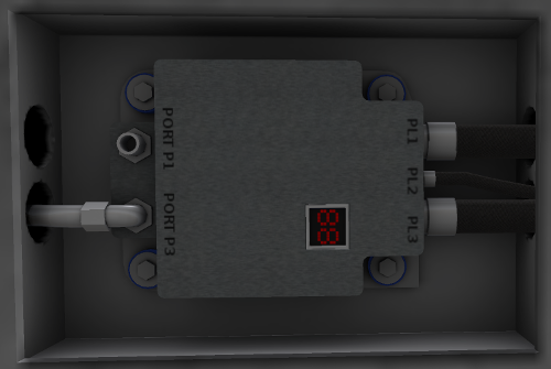
Two DECU units (see Figure 9), one for each engine, are mounted in the aft portion of the airframe near their respective engines. The DECUs contain the electronics for the primary and revisionary modes. Each DECU contains a two-digit hexadecimal BIT display indicating the operating status of the DECU.
On power-up, the DECU will undergo a self-check and systems check. During start, the BIT display will display 88 to indicate a successful start, or a fault code to indicate an error in the FADEC.
3.5 Engine Instruments and Cautions
The engine instruments are the N1 tachometer, the dual torquemeter, power turbine inlet temperature (PTIT), fuel flow, oil pressure and oil temperature indicators.
The N1 tachometers, PTIT, oil pressure and oil temperature instruments are located in separate columns on the left side of the center instrument panels. The torquemeter is located in the pilot and copilot instrument clusters and has one needle for each engine. The fuel flow gauge is located on the right side of the center console.
For each engine, the following caution capsules illuminate in abnormal conditions:
- ENG 1(2) OIL LOW. This is illuminated when approximately 2 quarts of usable oil remains.
- ENG 1(2) CHIP DET. This is illuminated when metal particles in the oil system bridge a magnetic gap. If caution may indicate an impending engine failure.
- ENG 1(2) FAIL. This indicates an engine failure during start, or during flight.
4 Fuel System
4.1 Fuel System Overview
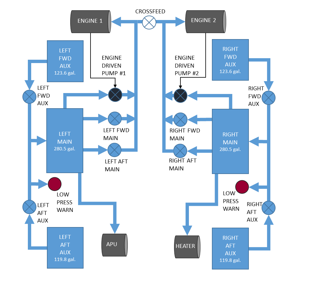
The fuel supply system (Figure 10) furnishes fuel to the two engines, the heater and the APU. Two separate systems connected by a crossfeed are installed. Each fuel system consists of a main tank, and forward and aft aux tanks.
4.2 Fuel System Control Panel
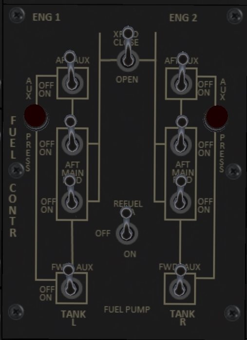
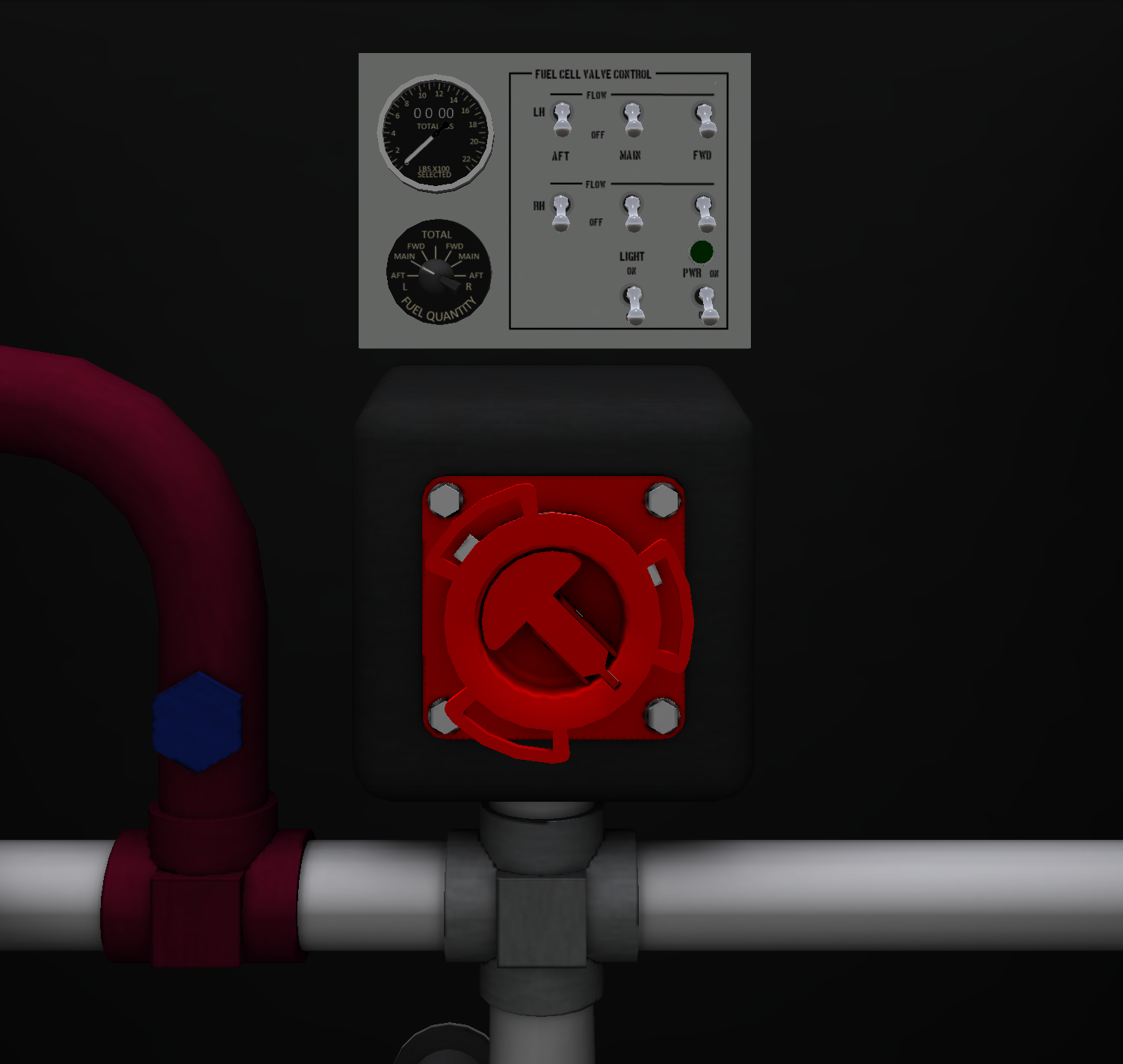
A simplified diagram of the fuel system is shown on the fuel system control panel (see Figure 11) located on the upper switch panel. Each AUX tank has a boost pump which transfers fuel from that AUX tank to the associated MAIN tank. When an AUX tank becomes empty, the pump will automatically shut off and a valve will close to prevent backflow of fuel from the main tank to the AUX tank. A low pressure warning light is installed for each side which illuminates when the pump switch is on, there is fuel remaining in an AUX tank and pressure is low. The low pressure warning lights will illuminate briefly when the pumps are first turned on.
Each main tank has two electrically driven boost pumps, and an engine driven pump. The boost pumps must be enabled for start, but once an engine is running fuel will continue to flow via the engine driven pumps as long as the helicopter is below 6000 feet pressure altitude. During normal operation, with all boost pumps operating, fuel is drawn from the main tanks and replenished by the AUX tanks.
A crossfeed switch labeled "XFEED" open a crossfeed valve connecting the two fuel systems. This allows an engine to draw fuel from the system of the opposite engine.
The fuel control panel also contains a switch to enabled the single-point refueling tanks. Internal electrical power must also be on to use the single-point refueling system.
4.3 Fuel Tank Capacities
| Tank | Gallons | Pounds |
|---|---|---|
| Right Front Aux | 119.2 | 810 |
| Right Main | 273.9 | 1862 |
| Right Aft Aux | 116.8 | 794 |
| Left Front Aux | 123.6 | 840 |
| Left Main | 280.5 | 1907 |
| Left Aft Aux | 119.8 | 814 |
4.4 Fuel Indicators
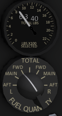
A fuel indicator and tank selector knob (see Figure 12) is located in the lower right corner of the center console. The indicator shows the remaining fuel in pounds of the selected tank, or the total fuel when TOTAL is selected. In addition, a 4-digit readout displays the total remaining fuel in pounds.
4.5 Gravity Refueling System
Each tank can be refueled individually with a gravity refueling system using KellyFuel. Three fuel tank caps are located on each sponson. To fuel a tank, touch the cap to toggle it on/off and use KellyFuel to check the fuel quantity or add fuel to the tank.
4.6 Pressure Refueling System
In addition to the gravity system, there is a single-point pressure refueling system that can be used to refuel all tanks from a single location (see (see Figure 13)). The single-point fueling station is located under a panel in the middle of the right sponson. To power the system, the battery and fueling station switches in the cockpit must be in the ON position, as well as the fuel station master switch on the fueling station panel. A green light over the fueling station master switch will indicate the system is energized.
Once the system is energized, individual switches can select which tanks will receive fuel. Any single tank, all tanks or any combination of tanks may be selected. In addition, a fuel gauge in the fueling station can be used to read the current fuel quantity.
5 Flight Controls and AFCS
5.1 Flight Controls
The helicopter is controlled by changing the pitch of the blades collectively or cyclically. Pitch changes are made through the flight controls which include a thrust control lever (similar to collective), a cyclic control stick and directional pedals. The pilot and copilot controls are interconnected and move together.
The thrust control lever collectively increases the pitch of all blades, controlling the helicopter vertically. The directional pedals control direction by imparting equal and opposite cyclic input to the forward and aft rotors. Lateral movement is controlled through the left/right cyclic which imparts equal cyclic input to both rotors. Finally longitudinal movement is controlled via the cyclic stick by imparting differential collective on the forward and aft rotors. See SECTION 1 - General for details on the Second-Life control options.
5.2 AFCS
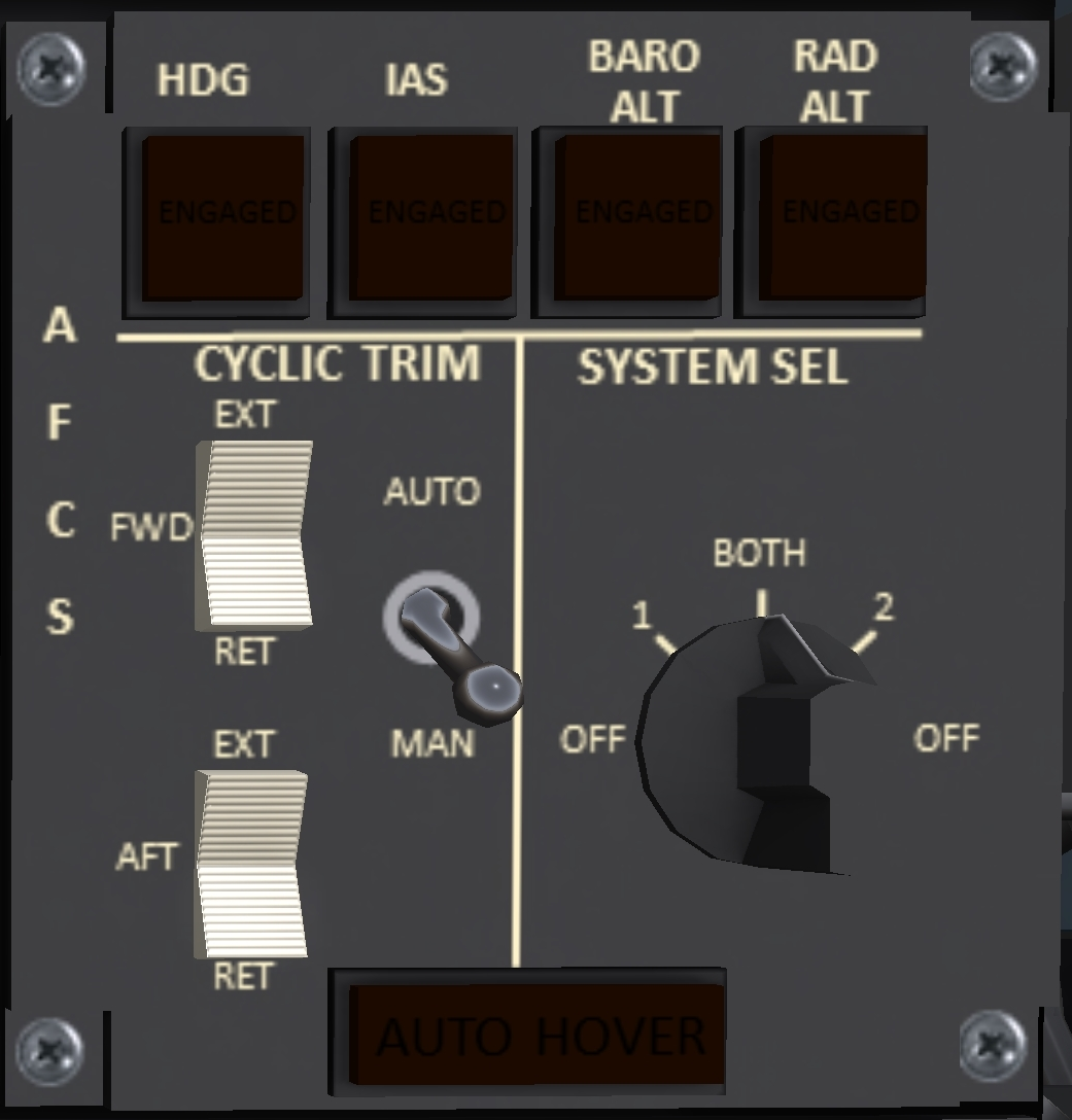
The Advanced Flight Control System (AFCS) can be used to reduce pilot workload by maintaining one or more flight axes of the helicopter. It can be used to maintain airspeed, heading, altitude or any combination of these. The system is comprised of two AFCS computers, sensors, actuators and a common AFCS control panel (see Figure 14). The AFCS panel also includes the controls for the cyclic trim described in the next section.
The Chinook is equipped with two AFCS systems controlled through the panel, the #1 and #2 systems. The #1 AFCS operates on the #1 AC bus and the #1 FC hydraulics, while the #2 AFCS uses the #2 AC bus and #2 FC hydraulics. A SYSTEM SELECT knob on the AFCS panel selects which AFCS systems to use with positions for OFF, #1, #2 and both. Normaly, both systems should be used. Performance will be degraded when using a single system.
At the top of the AFCS panel are four "hold" buttons. Turning on a hold causes the selected quantity to be maintained automatically by the AFCS. The following four holds can be maintained:
- HDG - Holds heading. Below 40 knots, heading will be maintained with pedals, and above 40 knots with lateral cyclic. When enaged, the current heading will be held. You can change the heading either through chat command, or by turning the heading bug on the HSI.
- IAS - Holds the Indicated Airspeed you were maintaining when the button was engaged. The hold airspeed can be changed through chat commands.
- BARO ALT - Holds the altitude at the time you engaged the hold. Target altitude can be changed through chat commands.
- RAD ALT - Holds the radar altitude (above ground level) at the time you engaged the hold. Radar altitude can only be used to the limit of the radar altimeter. Target altitude can be changed through chat commands.
In addition to the hold buttons is an AUTOHOVER button at the bottom of the AFCS panel. Engaging AUTOHOVER will set holds on heading, airspeed and altitude and set the hold airspeed to zero. Pressing AUTOHOVER again while already in an autohover will disengage the autotpilot.
5.3 AFCS Chat Commands
| Command | Description |
|---|---|
| ap IAS | Toggle airspeed hold |
| ap ALT | Toggle altitude hold |
| ap RALT | Toggle radar altitude hold |
| ap HDG | Toggle heading hold |
| ap HVR | Enter autohover mode |
| ap DIS | Disconnect autopilot |
| ap IAS n | Set the target airspeed to n |
| ap HDG n | Set the target heading to n |
| ap L n | Set the target heading left by n degrees |
| ap R n | Set the target heading right by n degrees |
| ap ALT n | Set the target altitude to n feet |
| ap RALT n | Set the target altitude to n feet above ground |
| ap D n | Set target altitude up n feet |
| ap U n | Set target altitude down n feet |
5.4 Cyclic Trim System
Associated with the AFCS is a cyclic trim system. The cyclic trim has a two position switch to select between AUTO and MAN (manual). When in auto mode, the longitudinal attitude of the helicopter will adjust as airspeed increases to result in a more level attitude in flight. This reduces drag and thus increases the maximum airspeed. The current state of the forward and aft rotor trim is displayed on two trim indicator gauges (see Fig. 2-4, Item 10). The trim indicators have a GND (ground) position which is used when the helicopter is on the ground. This gives the helicopter a slight nose up attitude when first picking up which transitions to a more level attitude once the wheels break contact with the ground.
When in manual mode, forward and aft rocker switches can manually extend and retract the blade trim. When extended, the helicopter will take an increasingly nose up attitude. This can be used in a hover to adjust the helicopter for a more nose up or more level attitude in landing.
6 Hydraulic System
6.1 General
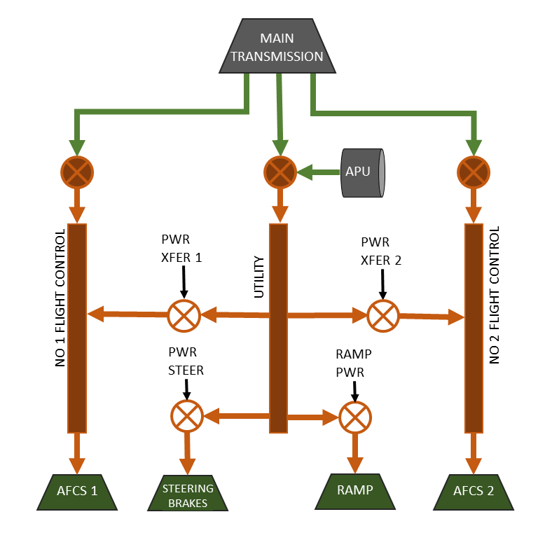
The Chinook has two flight control hydraulic systems and a utility hydraulic system (see Figure 15). The flight control hydraulic systems are powered by the main drive shaft and are normally pressurized when rotor RPM is above 70%. The Utility drive is powered by the accessory drive which is powered either by the main rotor drive shaft or by the APU.
Alert lights in the cockpit indicate when the pressure of any of the hydraulic systems are low. More detailed monitoring of the hydraulic systems is available to the flight engineer on the maintenance panel in the back of the aircraft (See SECTION 9 - Servicing for details).
6.2 Hydraulic Panel
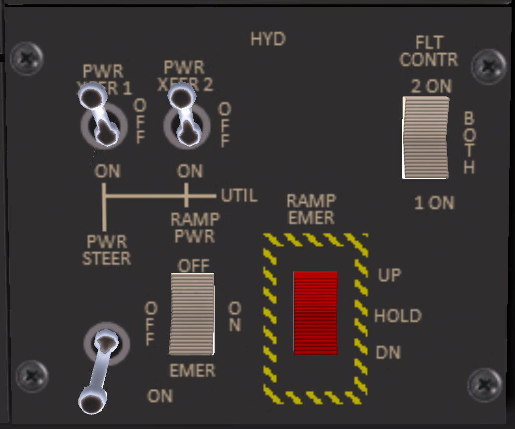
The hydraulic systems are controlled through a panel on the upper panel (see Figure 16). The hydraulic panel includes the following switches:
- PWR XFER 1(2) - When in the ON position, transfers power from the utility hydraulic system to the #1(2) Flight Control System. This can be used during start up to provide hydraulics for the flight controls before the main engines are started and during spin up of the main rotors.
- FLT CONTR - Selects which flight control hydraulic systems are used. Normally, BOTH should be selected, but can be set to a single system when one of the systems has failed to reduce drag on the controls.
- PWR STEER - When in the ON position, powers the hydraulic subsystem for the brakes and steering from the utility hydraulic system.
- RAMP PWR - Three position switch with OFF, ON and EMER positions. When in the OFF position, hydraulic power to the ramp is disabled. When in the ON position, normal hydraulic power to the ramp is available. When in the EMER position, the ramp can be controlled through the emergency ramp switch next to it.
- RAMP EMER - Allows the ramp to be controlled directly from the cockpit. The RAMP PWR switch must be in the EMER position to use this switch.
7 Power Train System
Engine power is supplied to the rotors through a mechanical transmission system. This system consists of a forward, a combining, an aft and two engine transmissions. An overruning sprag clutch in each engine transmission allows the rotor system to continue turning in the event of an engine failure.
The combining transmission combines power from each engine transmission, reduces the rotation speed, and transmits the combined power to the aft and forward transmissions. The aft and forward transmissions perform a further speed reduction before applying their output to the rotors.
The transmission can be monitored from the cockpit through pressure and temperature gauges as well as alert lights indicating when tolerances are exceeded. shows the pressure and temperature gauges for the transmission. Below each gauge is a selector to indicate which system to display. In addition to the single system settings there is a SCAN position that displays the highest system temperature on temperature gauge, and the lower pressure on the pressure gauge.
8 Rotor System
Lift is produced by two fully articulated counter-rotating rotors. Each rotor has three blades and is driven through a transmission. The rotor RPM is displayed on pilot and co-pilot side tachometers (see Figure 2, Item 16). The tachometers include an inner needle that displays percent RPM from 0-60, and an outer needle that displays RPM above 60%.
9 Electric System
9.1 Overview
The Chinook electrical system (see Figure 19) consists of two AC buses and two DC buses. The AC buses are powered by two primary generators or by an APU generator which produce 115V at 400 Hz. The DC system operates at 28 volts which is powered through rectifiers from each AC bus, or from a 24-volt nickel-cadmium battery.
The AC buses are connected by two AC bus ties. The bus ties are controlled by gang bar switches located near the bottom of the Power Distribution Panels (PDP) located behind and to side of the pilot and copilot seats. The #1 PDP is located near the co-pilot seat, while the #2 PDP is located near the pilot seat.
A hot battery bus supplies power to several devices even when the BATT switch is OFF. These devices include the digital clock, the APU control circuit, and the fluid level check for the maintenance panel.
9.2 Electrical Panel
The electrical system is controlled through the electrical panel (see ) located on the co-pilot side of the overhead panel. The electrical panel includes the following switches:
- BATT - When in the ON position, energizes the DC bus from the main battery.
- APU - Three position switch with OFF, RUN and START positions. The START position is spring loaded to the RUN position. The APU is started by holding the switch in the RUN position for 2-3 seconds, then releasing. It may be necessary to click once to move from OFF to RUN, then again to hold in the START position.
- GEN 1 - Supplies AC power to the #1 AC bus. The generator is powered off the aft transmission and is powered when the rotor RPM is above 70%.
- GEN 2 - Supplies AC power to the #2 AC bus. The generator is powered off the aft transmission and is powered when the rotor RPM is above 70%.
- APU GEN - Supplies AC power to the #1 AC bus when the APU is running.
10 Utility Systems
10.1 Anti-Ice
Anti-icing is provided for the pitot tubes and the windshield. An anti-ice panel is located on the overhead panel with individual switches for each of the systems. Heat for the windshield anti-ice is provided through a conductive film between layers.
10.2 Cabin Heat
The cabin heat panel is located on the overhead panel on the copilot side. The panel consists of a temperature select knob, a three position mode switch, and a start button for the heater. The mode switch has position BLR ONLY for only the blower, and OFF position, and a HTR position for the heater. To use the heater place the mode switch in the HTR position, then press the HTR START button to start the heater. For SL purposes, the heater is primarily for RP, but does include blower sounds.
10.3 Windshield Wipers
Windshield wiper controls are located to the right of the heater controls. It consists of single 5-position rotary switch. The wiper controls are for RP only in SL.
10.4 Maintenance Panel
The maintenance panel is on the right side of the aircraft above the ramp. The maintenance panel is used to help diagnose system malfunctions and should be periodically monitored during flight by the flight engineer. For details on the maintenance panel, see SECTION 9 - Servicing, Section 3.
11 Lighting
11.1 External Lighting
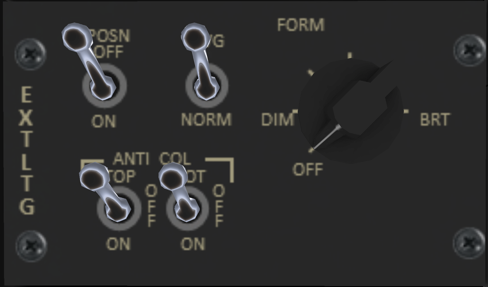
The external lighting panel (see Figure 22) includes the following switches:
- ANTI COL - Two separate switch control the top and bottom anti-collision lights. The anit-collision lights flash red and should normally be on any time the rotors are turning, or are about to start turning.
- POSN - Controls the position lights. The position lights consist of a red light on the left sponson, a blue/green light on the right sponson, and a white light on the aft side of the aft pylon. Position lights should be used between sunset and sunrise, as well as during a total solar eclipse.
- FORM - A six position knob controlling the intensity of the formation lights with an OFF position, and 5 intensity levels. Formation lights are for use at night when flying in multi-aircraft formations to improve visibility and aid in identification of the aircraft. There are two type of formation lights: normal and NVG (Night-Vision Goggles).
- NORM/NVG - Selects which set of formation lights should be used. When NORM is selected, the normal rectangular-shaped formation lights are used. When NVG is selected, the round night-vision formation lights are used.
11.2 Pilot Lighting
The pilot lighting panel (see Figure 23) is located on the pilot side of the overhead panel. It includes the following switches:
- PLTSRCHLT - Pilot side Search (Landing) Light
- CTR INST - Selectable intensity center instrument lights.
- PLT INST - Selectable intensity pilot instrument lights.
11.3 Co-Pilot Lighting
The copilot lighting panel (see Figure 24) is located on the pilot side of the overhead panel. It includes the following switches:
- CPLTSRCHLT - Co-Pilot side Search (Landing) Light
- CPLT INST - Selectable intensity copilot instrument lights.
- OVHD CSL - Selectable intensity overhead console lights.
11.4 Auxiliary Lighting
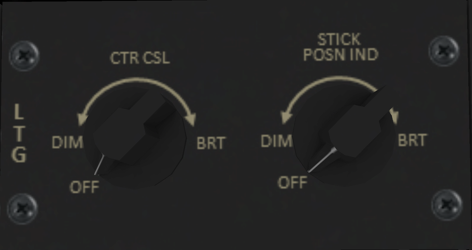
An auxiliary light panel is located at the top center of the overhead panel (see Figure 25). The panel contains two rotary switches. The left switch controls the light intensity of the center panel between the pilot and copilot seats. The right position is for the optional stick position indicator (not installed in this aircraft).
11.5 Internal Lighting
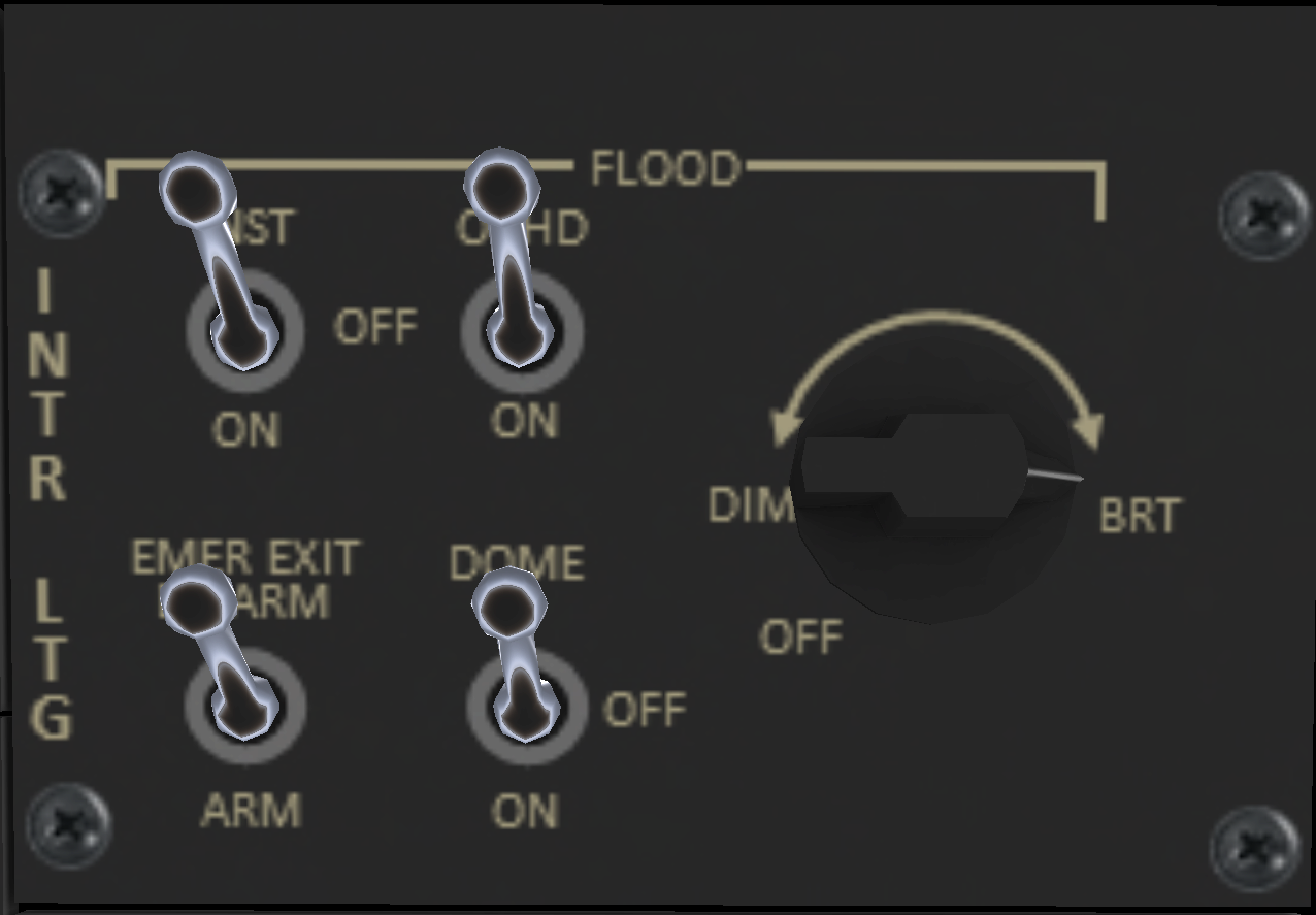
The internal lighting panel (see Figure 26) is located on the pilot side of the overhead panel. It includes the following switches:
- INST - Instrument flood lights are located under the instrument sun visor. Brightness is controlled by the near by knob with an OFF position, and multiple brightness levels from *DIM to OFF. Instrument flood lights will illuminate only if this switch is ON and the brightness knob is at a setting other than OFF.
- OVHD - Over flood lights are located on the bulkhead behind the pilot and copilot seats. Brightness is controlled by the near by knob with an OFF position, and multiple brightness levels from DIM to OFF. The overhead flood lights will illuminate only if this switch is ON and the brightness knob is at a setting other than OFF.
- EMER EXIT - Arms or disarms the emergency exit lights. These are described in the next section.
- DOME - Turns on the overhead dome lights over and slightly behind the pilot and copilot seats.
12 Master Alert/Caution Panel
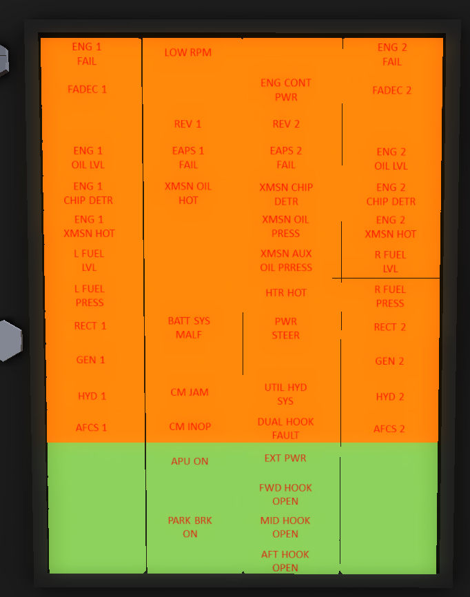
An alert and caution light panel is located on the center console. The panel consists of 4 columns of 16 lights. The upper 12 rows indicate abnormal conditions, while the bottom four (colored green) indicated advisory conditions. Each alert light indicates a malfunctioning or non-operative system. While it is normal for some alert lights to be illuminated before engine start, in general all alert lights should be off before attempting flight, and precautionary landing should be considered when any lights indicate while in flight. A complete list of the lights and their meaning are given in Appendex - Advisory Panel.
Two master caution lights on the pilot and copilot sides illuminate when any of the alert lights other than the green advisory lights illuminate. The master caution light can be dismissed by pressing it. When dismissed, the master caution light will come on again if any new alert lights illuminate.
